PWM modulation method and system for multi-module motor, vibration and common mode current suppression

A modulation method and common mode current technology, applied in control systems, current controllers, motor control, etc., to achieve the effects of reducing vibration noise, high power density, and suppressing common mode currents

Active Publication Date: 2021-10-08
HUAZHONG UNIV OF SCI & TECH +1
View PDF6 Cites 0 Cited by
  • Summary
  • Abstract
  • Description
  • Claims
  • Application Information

AI Technical Summary

Problems solved by technology

[0005] Aiming at the defects of the prior art, the object of the present invention is to provide a multi-module motor, a PWM modulation method and system for vibration and common mode current suppression, aiming at solving the problem that the existing multi-module motor control needs to add additional coupling inductance to suppress high-frequency vibration noise On this basis, the degree of freedom of the multi-module motor is considered comprehensively, and the method of reverse winding and complementary PWM is used to suppress the common mode current of the motor and reduce the damage to the bearing.

Method used


Image

  • PWM modulation method and system for multi-module motor, vibration and common mode current suppression
  • PWM modulation method and system for multi-module motor, vibration and common mode current suppression
  • PWM modulation method and system for multi-module motor, vibration and common mode current suppression

Examples


Embodiment Construction

[0036] In order to make the object, technical solution and advantages of the present invention clearer, the present invention will be further described in detail below in conjunction with the accompanying drawings and embodiments. It should be understood that the specific embodiments described here are only used to explain the present invention, not to limit the present invention.

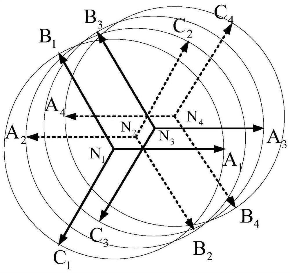
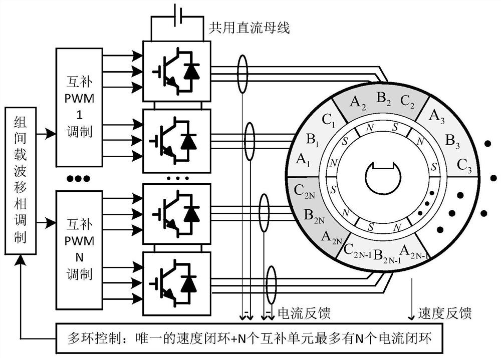
[0037] The invention proposes a multi-module motor, the stator of which is composed of an even number of Y-connected three-phase windings, each set of windings has the same impedance, and the neutral points are not connected to each other, here it is expressed as 2N sets of three-phase windings, and N is greater than 2 positive integer. There is very little magnetic circuit coupling between each set of windings, which avoids the increase of winding current ripple caused by the circulating current after carrier phase shifting, so the coupling inductance is unnecessary.

[0038] From a structural po...


PUM


Abstract

The invention discloses a multi-module motor, a PWM modulation method and system for suppressing vibration and common mode current. The motor stator is composed of an even number of sets of Y-connected three-phase windings, and the back electromotive force of the two sets of windings in the complementary unit differs by 180° in electrical angle. , the back electromotive force is the same between each complementary unit. The method includes adopting the classic inner and outer loop control framework, obtaining the current command value in the closed loop of the speed, and obtaining the modulation wave in the closed loop of the current; determining the carrier phase of each complementary unit, and modifying the PWM modulation action inside the complementary unit so that the two sets of windings in the complementary unit correspond to each other. The phase PWM is always reversed; the modulation wave is compared with the carrier, and the PWM wave is output according to the modified modulation action, which is output to the three-phase voltage source inverter to drive the entire motor. The control scheme proposed by the invention makes full use of its degree of freedom, takes into account its performance to the greatest extent, does not add additional equipment, reduces the vibration noise of the motor at the switching frequency, and can effectively reduce the common mode current of the motor control system.

Description

technical field [0001] The invention belongs to the field of electric transmission systems, and more specifically relates to a PWM modulation method and system for multi-module motors, vibration and common-mode current suppression. Background technique [0002] With the wide application of motor drive systems, people's demand for variable speed transmission power continues to increase, especially in metallurgical steel rolling, mine hoisting, locomotive traction, ship propulsion and other applications. Usually, the parallel connection of switching devices is not used, but the parallel connection of inverters is used to drive multi-phase motors or multi-module motors to increase capacity, which also improves the reliability of the system at the same time. [0003] In fact, multi-module motors have appeared for a long time. Because of the convenience brought by modularization, PWM modulation has more degrees of freedom, so that more problems can be solved. For high-power moto...

Claims


Application Information

Patent Timeline
Patent Type & Authority Patents(China)
IPC IPC(8): H02P6/10H02P6/28H02P25/022H02P25/22H02P27/12
CPCH02P6/10H02P25/022H02P25/22H02P27/12H02P2207/05H02P6/28
Inventor 刘自程刘康蒋栋何忠祥
Owner HUAZHONG UNIV OF SCI & TECH
Why Eureka
Try Eureka