Camera module pressure test structure

A camera module and stress testing technology, which is applied in image communication, television, electrical components, etc., can solve the problems of cumbersome operation and low efficiency, and achieve high test accuracy, convenient use, and accurate and reliable results

Pending Publication Date: 2020-11-06
ZHUHAI CITY GUANGHAOJIE PRECISION MACHINERY
View PDF0 Cites 2 Cited by
  • Summary
  • Abstract
  • Description
  • Claims
  • Application Information

AI Technical Summary

Problems solved by technology

In the past, when measuring the stability of the camera module, the operation was cumbersome and the efficiency was low

Method used


Image

  • Camera module pressure test structure
  • Camera module pressure test structure

Examples


Embodiment Construction

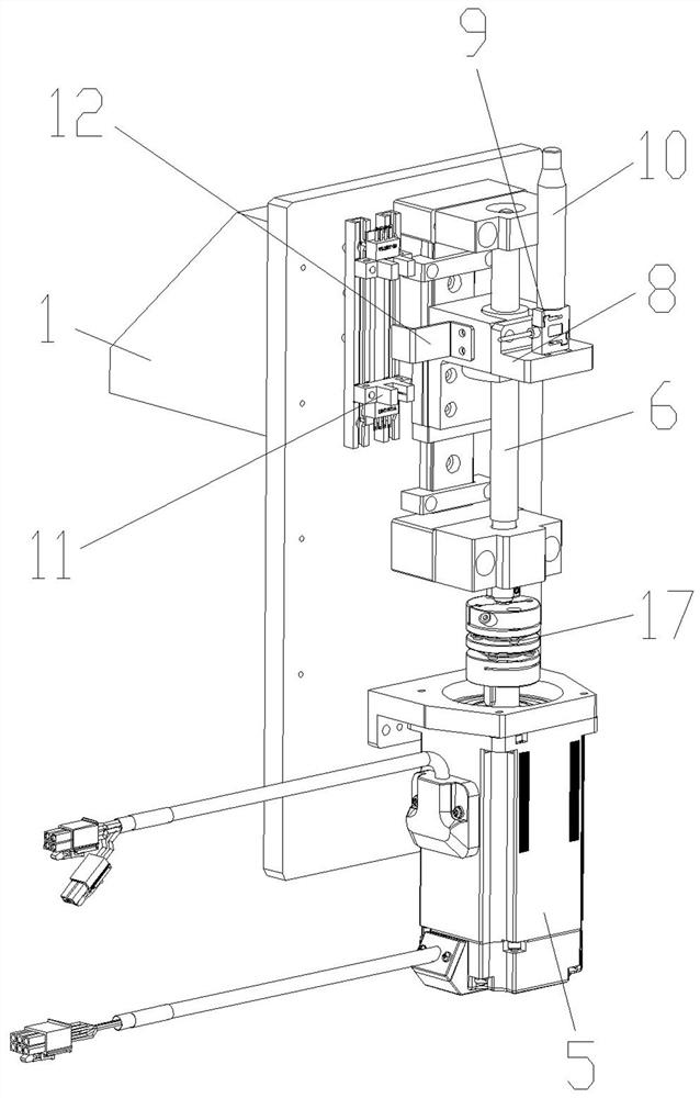
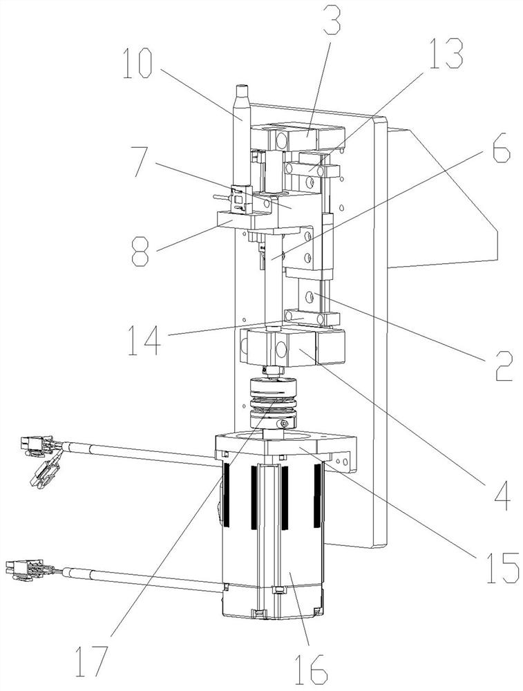
[0013] Such as Figure 1 to Figure 2 As shown, in this embodiment, the present invention includes a mounting seat 1, on which a guide rail assembly 2, an upper bearing seat 3, a lower bearing seat 4 and a drive module 5 are arranged, and the upper bearing seat 3 and A threaded mandrel 6 is cooperatingly arranged between the lower bearing seats 4, a threaded mandrel seat 7 is slidably arranged on the guide rail assembly 2, the threaded mandrel 6 is arranged on the said threaded mandrel seat 7, and on the said threaded mandrel 6 A top block 8 is provided, and a pressure sensor 9 is provided on the top block 8 , and a thimble 10 is provided on the pressure sensor 9 , and the driving module 5 is in transmission cooperation with the screw rod 6 . Compared with the deficiencies of the prior art, in the present invention, during the test, the screw rod 6 drives the jack block 8 to move upward through the drive module 5, so that the upper end of the ejector pin 10 can be fixed to the ...


PUM


Abstract

The invention discloses a camera module pressure test structure, and aims to provide a camera module pressure test structure which is convenient to use, easy to control and adjust and high in test precision. The structure comprises a mounting seat, a guide rail assembly, an upper bearing seat, a lower bearing seat and a driving module are arranged on the mounting seat; a lead screw is arranged between the upper bearing seat and the lower bearing seat in a matching mode. The guide rail assembly is provided with a lead screw seat in a sliding mode, the lead screw is arranged on the lead screw seat, the lead screw is provided with an ejector block, the ejector block is provided with a pressure sensor, the pressure sensor is provided with an ejector pin, and the driving module is in transmission fit with the lead screw. The structure is applied to the technical field of pressure testing structures.

Description

technical field [0001] The invention relates to a pressure test structure, in particular to a camera module pressure test structure. Background technique [0002] At present, all kinds of products are developing in the direction of portability and lightness, especially in the field of mobile phones, which require more functions in the limited space of the mobile phone, which makes the body structure design more compact. Therefore, the assembly position of the camera module is often compressed. When the camera module is assembled into the whole machine, it will be subjected to pressure from all directions, which will affect the imaging quality and function of the camera module. Therefore, when producing the camera, it is necessary to measure the stability of the camera module in different working environments. In order to increase the qualified rate of products. In the past, when measuring the stability of the camera module, the operation was cumbersome and the efficiency wa...

Claims


Application Information

Patent Timeline
Patent Type & Authority Applications(China)
IPC IPC(8): H04N17/00
CPCH04N17/00
Inventor 王寅岳学明
Owner ZHUHAI CITY GUANGHAOJIE PRECISION MACHINERY
Why Eureka
Try Eureka