Sheep fixing device

A technology of fixing device and positioning frame, which is applied in the fields of animal taming device, medical science, and apparatus for restraining animals, etc. good effect

Pending Publication Date: 2020-11-10
长兴昌达羊业有限公司
View PDF12 Cites 1 Cited by
  • Summary
  • Abstract
  • Description
  • Claims
  • Application Information

AI Technical Summary

Problems solved by technology

[0004] The above-mentioned existing fixing devices are too closed for fixing sheep, are not flexible enough to use, and are not very convenient. They are not very convenient for collecting sheep semen, trimming wool, breastfeeding, etc., and the effect is not very good.

Method used


Image

  • Sheep fixing device
  • Sheep fixing device
  • Sheep fixing device

Examples


Embodiment 1

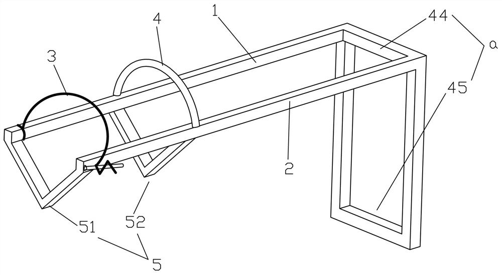
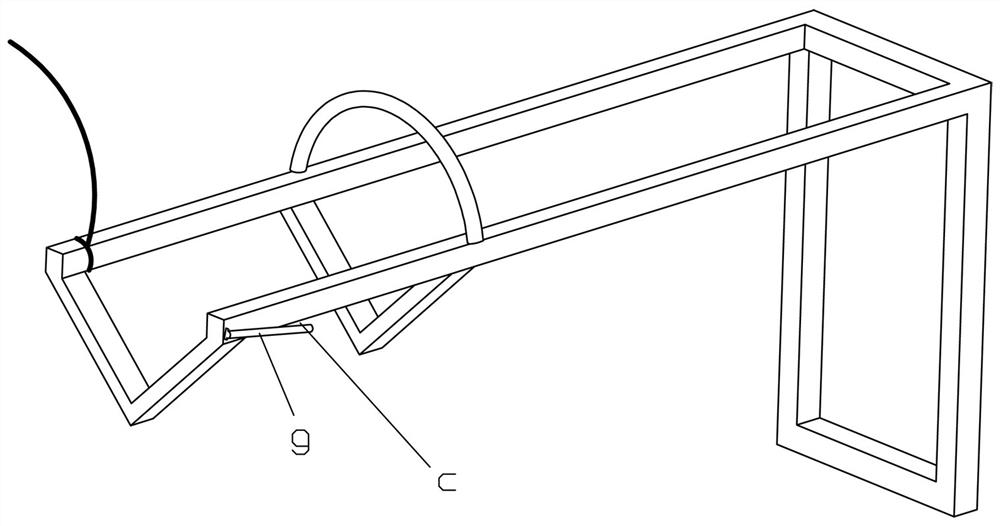
[0027] Example 1, such as Figure 1-3 As shown, a sheep fixing device includes left and right support rods 1 and right support rods 2 arranged side by side at intervals and extending in the front and rear directions, and can be arranged between the left support rod 1 and the right support rod 2 left and right. Between the rear limit bar 3 for limiting the back of the sheep's head and the front limit bar 4 for limiting the face of the sheep in front of the rear limit bar 3, the left support rod 1 and Right support bar 2 can adopt square steel pipe, and the two ends of rear limit bar 3 can be respectively installed and connected on described left support bar 1 and right support bar 2, and the two ends of front limit bar 4 can also be installed and connected respectively to On the left support rod 1 and the right support rod 2. The rear limit bar 3 is preferably detachably installed and connected to the left support bar 1 and the right support bar 2, while the front limit bar 4 ...

Embodiment 2

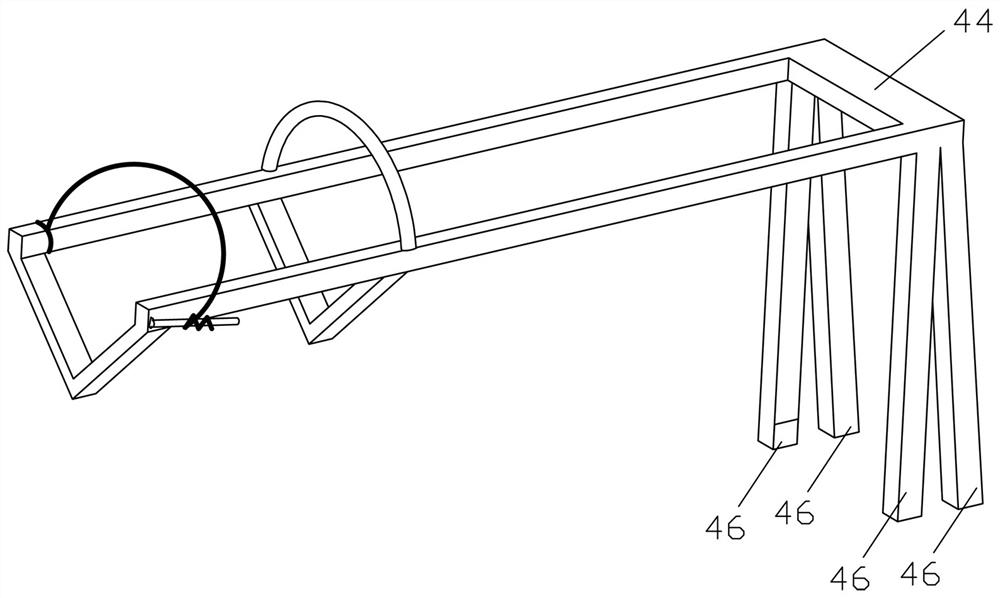
[0040] Example 2, such as Figure 4-5As shown, a sheep fixing device includes the sheep fixing device described in Embodiment 1, and also includes a sheep body positioning device for fixing the feet of the sheep. The structure of this kind of sheep fixing device can specifically be: comprising a sheep fixing device used to limit the position of the sheep head and a sheep body positioning device used to fix the sheep feet on the rear side of the sheep fixing device. The sheep fixing device has a left support rod 1 and a right support rod 2 arranged side by side at intervals and extending in the front and rear directions. The rear connecting rod z1 and the right rear connecting rod z2, the left rear connecting rod z1 and the right rear connecting rod z2 are arranged at intervals left and right, the left rear connecting rod z1 is fixed with a left column z10 extending downwards, the right A right upright z20 extending downward is fixed on the rear connecting rod z2, and the left...


PUM


Abstract

The invention relates to the technical field of livestock breeding equipment, in particular to a sheep fixing device. The sheep fixing device comprises a left supporting rod, a right supporting rod, arear limiting strip and a front limiting strip; the left supporting rod and the right supporting rod are arranged side by side in a left-right spaced manner and extend in the front-back direction, the rear limiting strip can be erected between the left supporting rod and the right supporting rod in a left-right crossing manner and is used for limiting the back sides of heads of sheep, and the front limiting strip is located in front of the rear limiting strip and is used for limiting the faces of the sheep; and the left supporting rod and the right supporting rod are installed on a positioning frame, and use is more flexible.

Description

technical field [0001] The invention relates to the technical field of animal husbandry equipment, in particular to a sheep fixing device. Background technique [0002] The existing equipment for fixing lambs is still being researched and developed. For example, the Chinese patent application number 201821914152.2 discloses a new type of sheep head fixing frame, including a cage body, a neck slot, a cage door, and a cage handle. , card slot handle, card slot switch, mouth ring and movable bracket. The cage body is a rectangular iron cage suitable for the size of the sheep. The upper end of one side is welded with a half circle as the lower card slot of the neck of the sheep. The upper part of the lower card slot is The upper card slot is formed by the semi-circle, and the neck of the sheep can be stuck in the two semi-circles; a movable bracket is welded on the iron cage under the groove, and a mouth ring is installed on the movable bracket to fix the sheep's mouth and nose....

Claims


Application Information

Patent Timeline
IPC IPC(8): A01K15/04A61D3/00
CPCA01K15/04A61D3/00A61D2003/003A61D2003/006
Inventor 李正秋殷雨洋李仁俊
Owner 长兴昌达羊业有限公司
Why Eureka
Try Eureka