Eureka AIR delivers breakthrough ideas for toughest innovation challenges, trusted by R&D personnel around the world.

Combined heat exchanger, heat exchange system and optimization method thereof

A technology of heat exchange system and heat exchange unit, applied in the field of heat exchange system

Pending Publication Date: 2020-11-10
CARRIER CORP
View PDF0 Cites 0 Cited by
  • Summary
  • Abstract
  • Description
  • Claims
  • Application Information

AI Technical Summary

Problems solved by technology

[0003] The purpose of the present invention is to solve or at least alleviate the problems existing in the prior art

Method used


Image

  • Combined heat exchanger, heat exchange system and optimization method thereof
  • Combined heat exchanger, heat exchange system and optimization method thereof
  • Combined heat exchanger, heat exchange system and optimization method thereof

Examples


Embodiment Construction

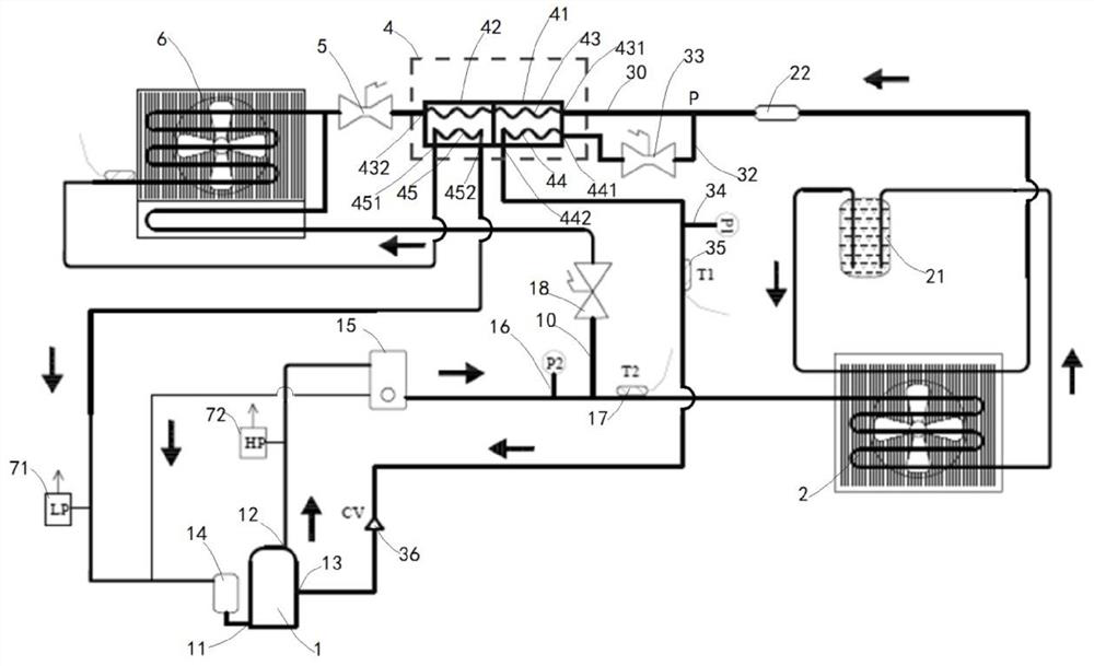
[0035] first reference figure 1 Let’s introduce the heat exchange system according to the embodiment of the present invention. This system can be used in various working conditions, especially for the refrigeration system of electric transport vehicles. sensitive. The heat exchange system includes: a steam enthalpy injection compressor 1 , a condenser 2 , an expansion valve 5 and an evaporator 6 in the main loop. The steam enthalpy injection compressor 1 includes a compressor inlet 11 , a compressor outlet 12 and a steam enthalpy injection port 13 . As shown in the figure, the high-temperature and high-pressure steam leaving the compressor outlet 12 of the heat exchange system passes through the oil separator 15 to separate the oil, and then returns to the compressor inlet 11 through the oil return pipe and the gas-liquid separator 14, while the refrigerant enters the condensation After leaving the condenser 2, the refrigerant passes through the liquid storage drier 21 and e...


PUM


Abstract

The invention provides a combined heat exchanger, a heat exchange system and an optimization method thereof. The heat exchange system comprises a first branch which is branched from a main loop at a branch point P on the downstream of a condenser and leads to a steam enthalpy spraying opening of the compressor, wherein a first heat exchange unit and a second heat exchange unit are further arrangedbetween the branch point P on the main loop and the expansion valve. A refrigerant leaving the condenser is divided into a first part passing through the first heat exchange unit and the second heatexchange unit from a main loop and a second part leading to the steam enthalpy spraying opening through the first branch at the branch point P; the second part of the refrigerant passes through a branch expansion valve and exchanges heat with the first part of the refrigerant in the main loop in the first heat exchange unit, and the first part of the refrigerant exchanges heat with the refrigerantflowing from the evaporator to the compressor inlet in the second heat exchange unit. The heat exchange system according to the present invention has improved performance and efficiency.

Description

technical field [0001] The present invention relates to the field of heat exchange systems, and more specifically, the present invention relates to a combined heat exchanger, a heat exchange system and an optimization method thereof, which are especially suitable for refrigeration systems of electric transport vehicles. Background technique [0002] Refrigeration systems on transport vehicles can be equipped with steam injection compressors. In this type of refrigeration system, a part of the refrigerant leaving the condenser can be throttled and introduced into the vapor injection inlet of the compressor, so that the discharge temperature of the compressor can be controlled without sacrificing system capacity. Contents of the invention [0003] The purpose of the present invention is to solve or at least alleviate the problems existing in the prior art. [0004] In one aspect, there is provided a heat exchange system, especially a refrigeration system for an electric tra...

Claims


Application Information

Patent Timeline
IPC IPC(8): B60H1/32
CPCB60H1/3227F25B40/00F25B47/022F25B2400/13F25B2500/08F25B2500/18F25B2600/2509F25B2700/21152F25B2700/1931F25B41/34Y02B30/70F25B41/48F25B40/06
Inventor 谢康山陈林辉谢飞
Owner CARRIER CORP
Why Eureka
Eureka Blog
Learn More