
High-altitude wind energy equipment being small in occupied area and capable of being mutually connected and separated

A technology of interconnection and occupation area, applied in the field of wind energy, can solve the problems of incomplete development of high-altitude wind energy, large floor space, dangerous accidents, etc., to achieve the effect of improving working time and efficiency, reducing floor space and improving stability

Inactive Publication Date: 2020-11-10
郑州夙烟新能源科技有限公司
View PDF0 Cites 0 Cited by
  • Summary
  • Abstract
  • Description
  • Claims
  • Application Information

AI Technical Summary

Problems solved by technology

[0002] As a widely distributed, large quantity, non-polluting and renewable energy, wind energy has been valued and developed by human beings. Today's wind power generation equipment can only use wind energy within 300 meters from the ground. For high-altitude wind energy higher than 300 meters The development is not perfect, high-altitude wind has the characteristics of high wind speed, wide distribution, and high stability, and the higher the distance from the ground, the greater the wind power and the stability. A lot of wind energy usually flies very high, but the higher the flight, the longer the rope, the farther the distance between the required equipment, the larger the area required for the base station, and the problem of dangerous accidents caused by the ropes being entangled with each other

Method used


Image

  • High-altitude wind energy equipment being small in occupied area and capable of being mutually connected and separated
  • High-altitude wind energy equipment being small in occupied area and capable of being mutually connected and separated
  • High-altitude wind energy equipment being small in occupied area and capable of being mutually connected and separated

Examples


Embodiment Construction

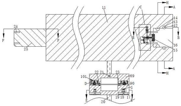
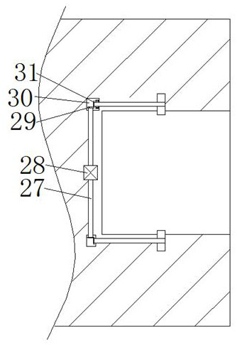
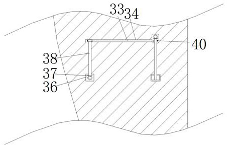
[0025] Combine below Figure 1-Figure 9 The present invention is described in detail, and for convenience of description, the orientations mentioned below are now stipulated as follows: figure 1 The up, down, left, right, front and back directions of the projection relationship itself are the same.

[0026]A high-altitude wind energy device that occupies a small area and can be connected and separated from each other according to the present invention includes an aircraft 11, a connecting block 25 is fixed in the center of the left end surface of the aircraft 11, and the left end of the connecting block 25 is arranged symmetrically up and down. There is a threaded cavity 24 with an opening to the left, and a connecting cavity 16 with an opening to the right is provided at the center of the right end of the aircraft 11, and a slider cavity 88 with an opening to the right is provided at the center of the left wall of the connection cavity 16. The cavity 88 is provided with a sl...


PUM


Abstract

The invention discloses high-altitude wind energy equipment being small in an occupied area and cable of being mutually connected and separated. The high-altitude wind energy equipment comprises an aircraft, a connecting block is fixedly arranged in the center of the left end face in the aircraft, threaded cavities with leftward openings are vertically and symmetrically formed in the left end in the connecting block, and a connecting cavity with a rightward opening is formed in the center of the right end in the aircraft; by means of the mode that connection is conducted firstly and then separation is conducted, the stability is improved through mutual connection of aerial vehicles working aloft, and then separation is conducted through the electricity storage box and the power box, so that the stability of the aerial vehicles working aloft is improved, and through separating an electricity storage box from a power box, the power box lands to the ground through the draught fan for electric power transmission, the working time and efficiency of the aircraft are improved, meanwhile, aircraft accidents caused by rope winding are reduced through the power box capable of ascending and descending linearly, the occupied area of the aircraft is also reduced, and the conversion efficiency of wind energy is improved.

Description

technical field [0001] The invention relates to the technical field of wind energy, in particular to high-altitude wind energy equipment that occupies a small area and can be connected and separated from each other. Background technique [0002] As a widely distributed, large quantity, non-polluting and renewable energy, wind energy has been valued and developed by human beings. Today's wind power generation equipment can only use wind energy within 300 meters from the ground. For high-altitude wind energy higher than 300 meters The development is not perfect, high-altitude wind has the characteristics of high wind speed, wide distribution, and high stability, and the higher the distance from the ground, the greater the wind power and the stability. A lot of wind energy usually flies very high, but the higher the flight, the longer the rope, the farther the distance between the required equipment, the larger the area required for the base station, and the problem of dangerou...

Claims


Application Information

Patent Timeline
Patent Type & Authority Applications(China)
IPC IPC(8): B64C1/00F03D1/00
CPCB64C1/00F03D1/00Y02E10/72
Inventor 周昆鹏
Owner 郑州夙烟新能源科技有限公司
Learn More