Bottle cap locking machine

A bottle cap lock and lock technology, which is applied in the direction of sealing machine, bottle capping machine safety/control, bottle/container cap, etc. It can solve the problems that the bottle cap is easy to tilt, the bottle cap is stuck and cannot enter the locker, etc. , to achieve the effect of smooth locking

Active Publication Date: 2020-11-10
上海宇田机电设备有限公司
View PDF9 Cites 2 Cited by
  • Summary
  • Abstract
  • Description
  • Claims
  • Application Information

AI Technical Summary

Problems solved by technology

[0003] When the existing locking machine locks the oral liquid bottle cap, the bottle cap is loose on the top of the bottle, so the bottle cap tends to be inclined, and it is ea

Method used


Image

  • Bottle cap locking machine
  • Bottle cap locking machine
  • Bottle cap locking machine

Examples


Embodiment 1

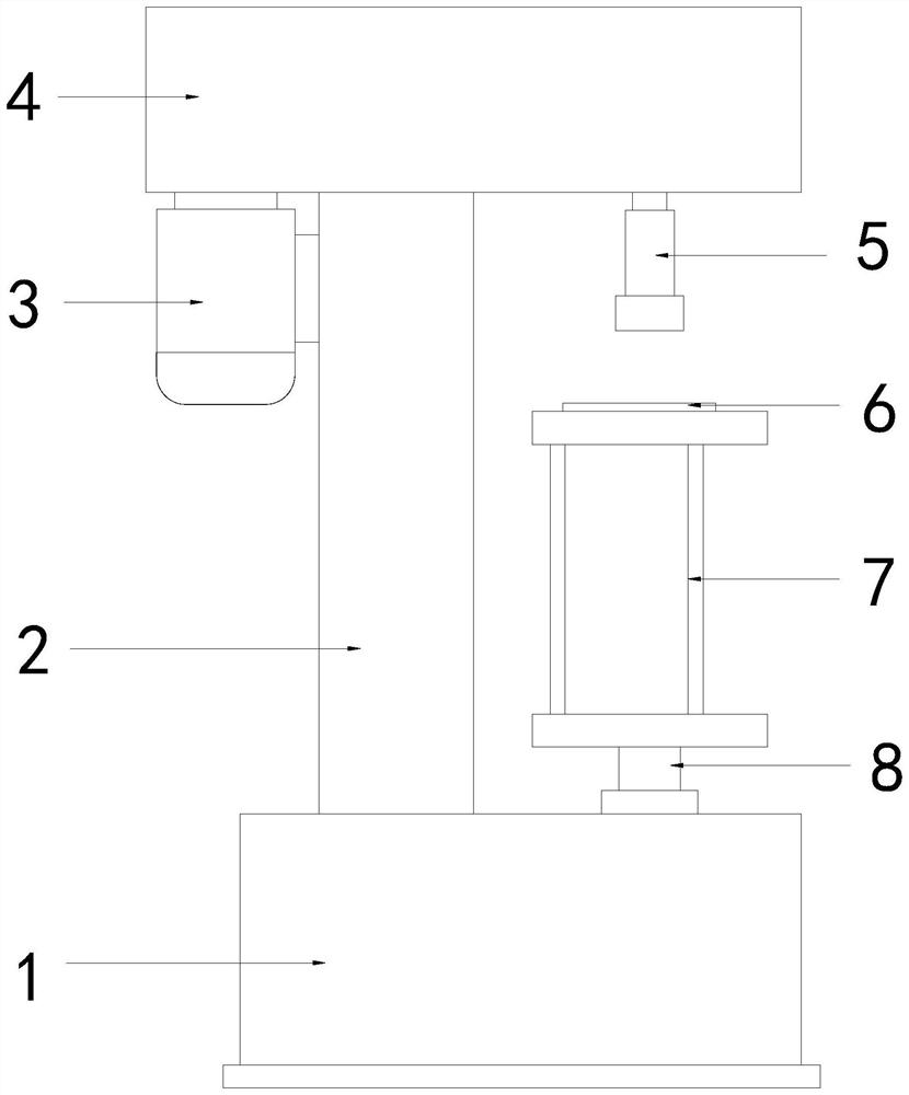
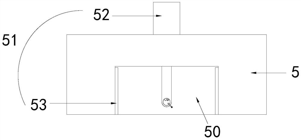
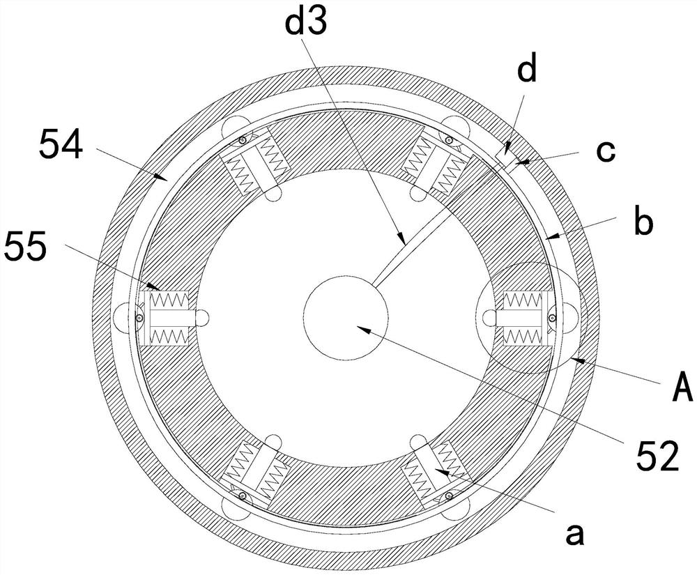
[0031] see Figure 1-6 , the present invention provides a technical solution for a bottle cap locking machine: its structure includes a base 1, a column 2, a motor 3, a transmission box 4, a locking device 5, a blade 6, a locator 7, and a rotating shaft 8. Above the base 1 Connected with a column 2, the top of the column 2 is connected with the transmission box 4, and the two ends of the transmission box 4 are respectively connected with a motor 3 and a locking device 5, and the locator 7 is located below the locking device 5 and the bottom Installed on the base 1 through a rotating shaft 8, a blade 6 is provided above the lock 5, a positioning groove 50 is provided in the middle of the bottom of the lock 5, a correction device 51 is installed on the lock 5, and the correction The device 51 includes a starting structure 52 and an adjusting device 53, the starting structure 52 is installed in the middle of the positioning groove 50, the adjusting device 53 is installed inside t...

Embodiment 2

[0034] see Figure 1-6, the present invention provides a technical solution for a bottle cap locking machine: its structure includes a base 1, a column 2, a motor 3, a transmission box 4, a locking device 5, a blade 6, a locator 7, and a rotating shaft 8. Above the base 1 Connected with a column 2, the top of the column 2 is connected with the transmission box 4, and the two ends of the transmission box 4 are respectively connected with a motor 3 and a locking device 5, and the locator 7 is located below the locking device 5 and the bottom Installed on the base 1 through a rotating shaft 8, a blade 6 is provided above the lock 5, a positioning groove 50 is provided in the middle of the bottom of the lock 5, a correction device 51 is installed on the lock 5, and the correction The device 51 includes a starting structure 52 and an adjusting device 53, the starting structure 52 is installed in the middle of the positioning groove 50, the adjusting device 53 is installed inside th...


PUM


Abstract

The invention discloses a bottle cap locking machine. The bottle cap locking machine structurally comprises a base, a column, a motor, a transmission case, a locking device, a blade, a positioner anda rotating shaft, wherein the column is connected to the upper part of the base; the top of the column is connected to the transmission case; the motor and the locking device are connected to the twoends of the transmission case respectively; the positioner is arranged below the locking device and installed on the base through the rotating shaft; the blade is arranged above the locking device; apositioning groove is arranged in the middle of the bottom of the locking device; the locking device is provided with a correcting device; the correcting device comprises a starting structure and an adjusting device; the starting structure is arranged in the middle of the positioning groove; the adjusting device is arranged in the locking device; and an annular groove is arranged in the locking device and communicates with the positioning groove through an installation groove. The bottle cap locking machine has the beneficial effects that an oral liquid bottle cap can be corrected and positioned through the correcting device, a situation that the bottle cap abuts against the edge of the positioning groove is avoided, and the locking is smoother.

Description

technical field [0001] The invention relates to the field of beverage packaging, in particular to a bottle cap locking machine. Background technique [0002] The locking machine is mainly used for the sealing of aluminum caps of various glass bottles, plastic and polyester bottle mouths, metal anti-theft caps, easy-open caps, aluminum caps and nozzle caps, thread pressing, and easy-open caps. Capping is an ideal equipment for capping and packaging small bottles of medicine, health care products, chemicals, cosmetics, etc. It is suitable for all kinds of glass, and is suitable for the necessary production equipment of beverage, wine, chemical, pharmaceutical, cosmetic and other manufacturers. [0003] When the existing locking machine locks the oral liquid bottle cap, the bottle cap is loose on the top of the bottle, so the bottle cap tends to be inclined, and it is easy to push against the edge of the positioning groove of the locking device after rising. The bottle cap is...

Claims


Application Information

Patent Timeline
IPC IPC(8): B67B3/00B67B3/26
CPCB67B3/00B67B3/262B67B2201/00
Inventor 蒋利水
Owner 上海宇田机电设备有限公司
Why Eureka
Try Eureka