Supercharge Your Innovation With Domain-Expert AI Agents!

Anti-winding mechanism of hank reeling machine

An anti-winding and twisting machine technology, applied to other manufacturing equipment/tools, textiles and papermaking, manufacturing tools, etc., can solve the problems of difficult yarn removal and easy entanglement, and achieve entanglement prevention, reasonable structure, and easy operation convenient effect

Inactive Publication Date: 2020-11-10
黄山市信达丝线有限公司
View PDF9 Cites 0 Cited by
  • Summary
  • Abstract
  • Description
  • Claims
  • Application Information

AI Technical Summary

Problems solved by technology

[0004] The purpose of the present invention is to solve the problem that existing skeining machine in the prior art is difficult to take off because the yarn is wound on the skein creel after the skeining machine is finished, and The shortcoming of winding is easy to occur, and a kind of anti-winding mechanism of twisting machine is proposed

Method used

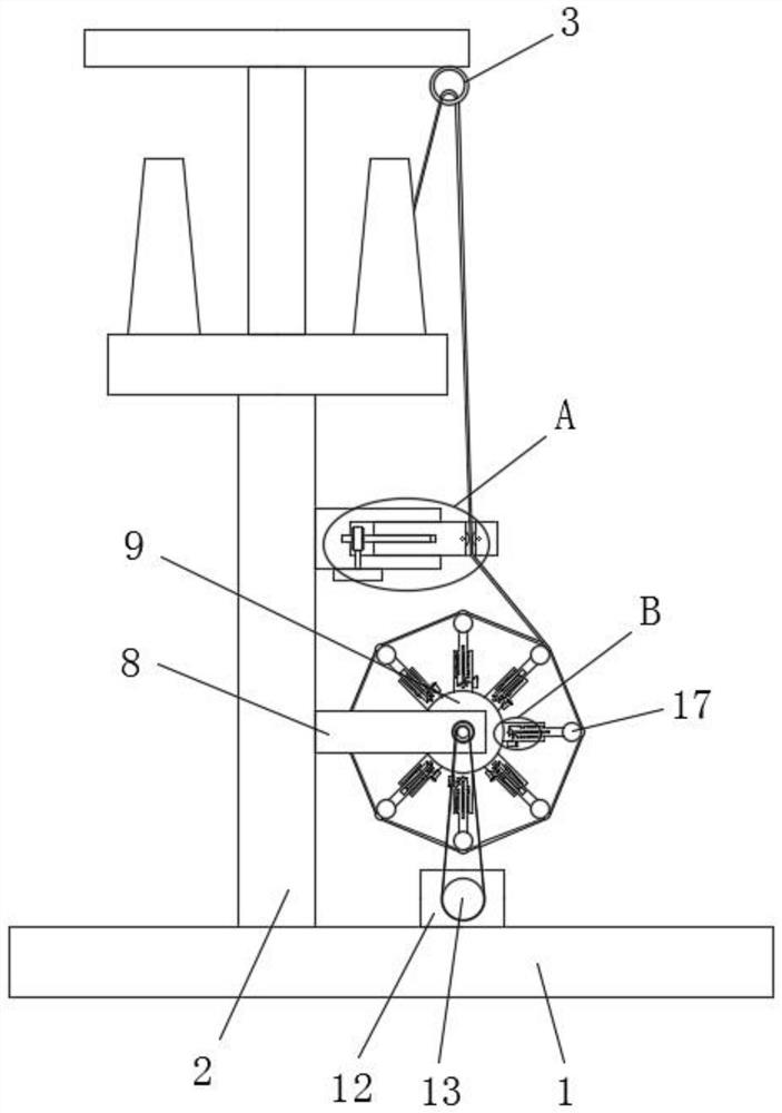

Image

  • Anti-winding mechanism of hank reeling machine
  • Anti-winding mechanism of hank reeling machine
  • Anti-winding mechanism of hank reeling machine

Examples


Embodiment 1

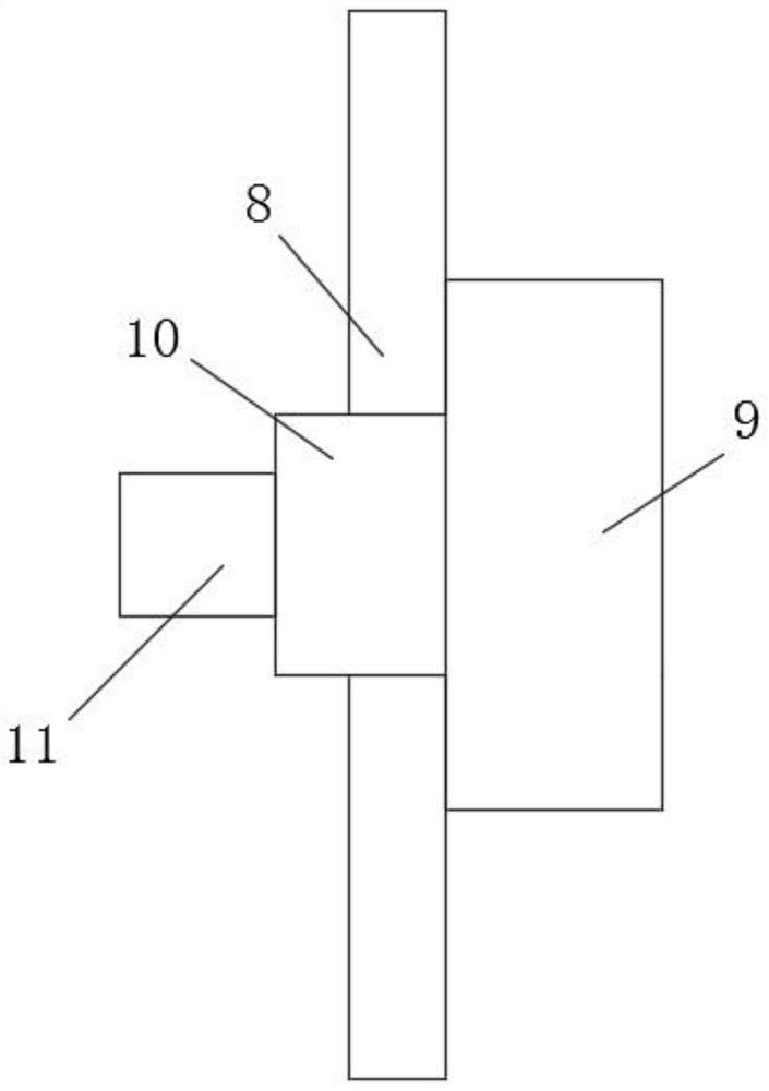
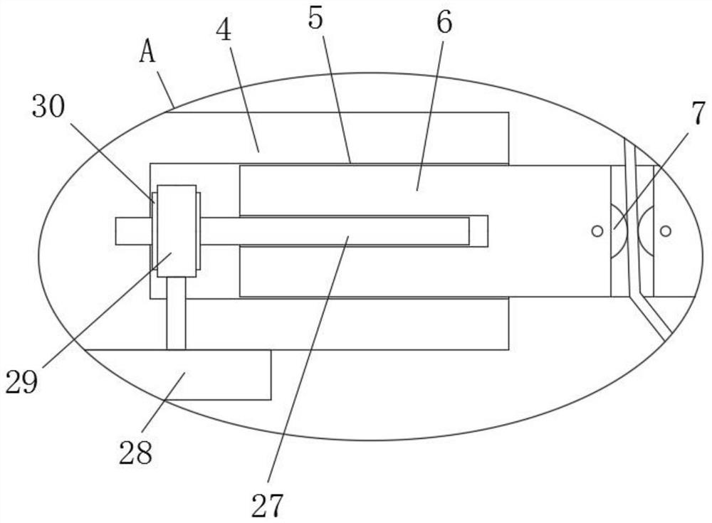
[0026] refer to Figure 1-5 , an anti-winding mechanism of a stranding machine, comprising a base plate 1, a stranding frame body 2 is fixedly installed on the top of the base plate 1, an anti-winding ring 3 is fixedly installed on the stranding frame body 2, and a stranding frame body 2 One side of the connecting column 4 is fixedly installed, and one end of the connecting column 4 is provided with a connecting groove 5, and the adjusting column 6 is slidably installed in the connecting groove 5, and the top of the adjusting column 6 is provided with an anti-winding hole, and the inner walls on both sides of the anti-winding hole An anti-winding wheel 7 is installed on the top, and an adjustment mechanism is arranged in the connecting groove 5. The adjustment mechanism is compatible with the adjustment column 6. A mounting plate 8 is fixedly installed on the frame body 2 of the stranding machine, and one side of the mounting plate 8 is opened. There is a rotating hole, and a ...

Embodiment 2

[0035] refer to Figure 1-5 , an anti-winding mechanism of a twisting machine, comprising a bottom plate 1, a twisting machine frame body 2 is fixedly installed on the top of the bottom plate 1 through bolts, and an anti-winding ring 3 is fixed on the twisting machine frame body 2 through bolts, and the twisting machine frame body 2 is fixed with an anti-winding ring 3. One side of the frame body 2 is fixed with a connecting column 4 by bolts, and one end of the connecting column 4 is provided with a connecting groove 5, and an adjusting column 6 is slidably installed in the connecting groove 5, and the top of the adjusting column 6 is provided with an anti-winding hole to prevent The inner walls of both sides of the winding hole are equipped with anti-winding wheels 7, and the connecting groove 5 is equipped with an adjustment mechanism, which is compatible with the adjustment column 6. The frame body 2 of the stranding machine is fixed with a mounting plate 8 by bolts. One s...


PUM


Abstract

The invention belongs to the field of hank reeling machines, particularly relates to an anti-winding mechanism of a hank reeling machine, and aims to solve the problems that yarn wound on a hank reeling frame is difficult to take down and easy to wind due to the fact that the yarn is wound on the hank reeling frame after an existing hank reeling machine completes hank reeling. The following schemeis provided, and the mechanism comprises a bottom plate. A hank reeling machine frame body is fixedly installed at the top of the bottom plate, an anti-winding ring is fixedly installed on the hank reeling machine frame body, a connecting column is fixedly installed at one side of the hank reeling machine frame body, a connecting groove is formed at one end of the connecting column, an adjustingcolumn is installed in the connecting groove in a sliding manner, an anti-winding hole is formed at the top of the adjusting column, and anti-winding wheels are rotationally installed on the inner walls of the two sides of the anti-winding hole. The anti-winding mechanism is reasonable in structure and convenient to operate, after hank reeling by the hank reeling machine is completed, the positionof a connecting rod can be adjusted, yarn on the hank reeling frame can be taken down conveniently, winding can be prevented through the arranged anti-winding ring and the arranged anti-winding wheels, and the maintenance rate of equipment is reduced.

Description

technical field [0001] The invention relates to the technical field of stranding machines, in particular to an anti-winding mechanism of the stranding machine. Background technique [0002] The twisting machine is a special twisting equipment in the textile field. Its function is to withdraw the tubed yarn through the twisting frame, change its packaging form, and facilitate the normal operation of the next process. The existing twisting machine includes a frame, a yarn Frame, spindle tray, yarn frame, motor, transmission shaft and guide wire rod and other components, the motor drives the transmission shaft to rotate, and the transmission shaft drives the yarn frame to rotate through transmission components such as belts and friction wheels, thereby transforming the yarn into the tube Into the twisted form to complete the twisting process; [0003] However, after the existing skeining machine is skeined, because the yarn is wound on the skein frame, it is difficult to take ...

Claims


Application Information

Patent Timeline
Patent Type & Authority Applications(China)
IPC IPC(8): D02H11/00D02H13/00
CPCD02H11/00D02H13/00
Inventor 江朝辉
Owner 黄山市信达丝线有限公司
Features
  • R&D
  • Intellectual Property
  • Life Sciences
  • Materials
  • Tech Scout
  • Unparalleled Data Quality
  • Higher Quality Content
  • 60% Fewer Hallucinations
Learn More