Shockproof pump shaft assembly for magnetic drive pump and magnetic drive pump

A magnetic pump and pump shaft technology, which is applied to pump elements, components of a pumping device for elastic fluids, pumps, etc., can solve the problems of damaged shaft sleeves, poor dynamic balance, and difficult processing, and achieve concentricity. Good compensation, avoiding direct contact and high processing uniformity

Pending Publication Date: 2020-11-10
YANKUANG GRP CO LTD
View PDF0 Cites 0 Cited by
  • Summary
  • Abstract
  • Description
  • Claims
  • Application Information

AI Technical Summary

Problems solved by technology

[0004] 1. The metal support ring is a sheet-like object, which is difficult to process and cannot achieve a high concentricity. The fit with the shaft sleeve is low and the dynamic balance is not good
[0005] 2. Magnetic pumps are generally used in high-temperature and corrosion-resistant working conditions, and the material requirements for the shaft sleeve support expansion ring are particularly high. Since the shaft sleeve expansion ring is in a running state, especially the shaft sleeve expansion ring is in the narrow space between the shaft sleeve and the shaft. In the space, it is more prone to corrosion and dirt deposition
After a period of use, the shaft sleeve support ring fails
[0006] 3. The installation operation is complicated. During the process of pressing the shaft sleeve into the supporting expansion ring, it is very easy to cause damage to the shaft sleeve. At the same time, in the later maintenance process of the magnetic pump, it is difficult to disassemble. Choosing to disassemble will cause unnecessary maintenance losses
[0007] 4. In a rubber expansion ring known to the inventor, it is formed by enclosing three toroids and an outer arc surface, and the inner torus of the three torus fits with the inner torus of the annular groove. The outer ring surface of the first ring surface fits the side ring surface of the annular groove, and the part participating in the elastic deformation is only the outer arc surface, which makes the annular groove must be deep enough, and the rubber expansion ring cannot provide enough elastic surplus. amount, it may cause wear between the sleeve and the pump shaft

Method used


Image

  • Shockproof pump shaft assembly for magnetic drive pump and magnetic drive pump
  • Shockproof pump shaft assembly for magnetic drive pump and magnetic drive pump
  • Shockproof pump shaft assembly for magnetic drive pump and magnetic drive pump

Examples


Embodiment 1

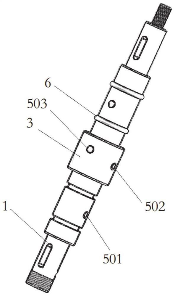
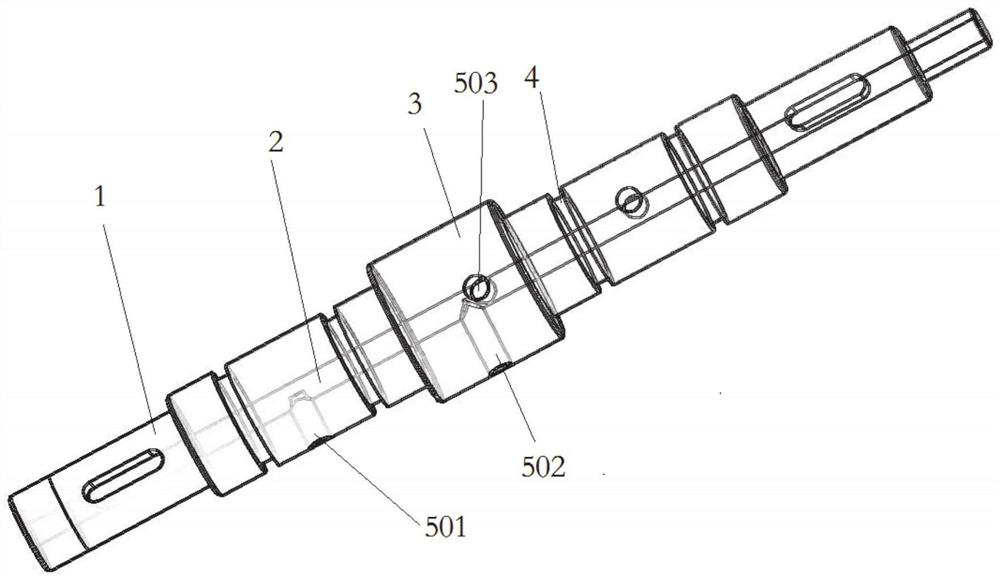
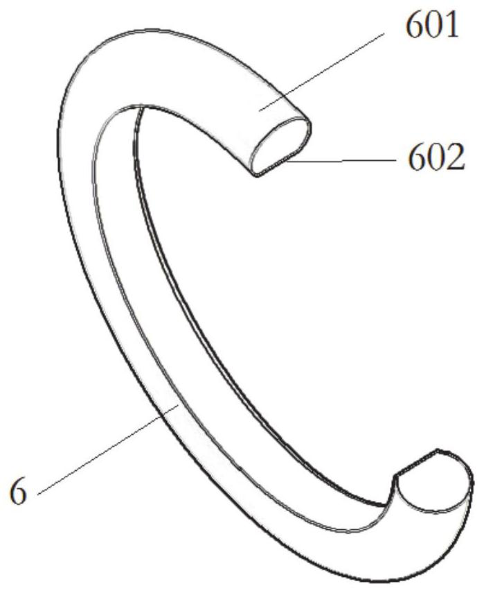
[0026] Such as Figure 1-Figure 3 As shown, a shock-proof pump shaft assembly for a magnetic pump is characterized in that it includes a pump shaft 1. A shaft sleeve is sleeved on the outer side of the pump shaft 1, and a rubber is provided between the shaft sleeve and the outer side of the pump shaft 1. Expanding ring 6, the outer side of the rubber expanding ring 6 is formed by a combination of an inner ring surface 601 and an outer arc surface 602, so that the cross-sectional profile of the rubber expanding ring 6 is D-shaped;

[0027] The outer circular side of the pump shaft 1 is provided with an annular groove 4, the inner ring surface 601 of the rubber expansion ring 6 fits the ring surface of the annular groove 4, and the outer arc surface 602 of the rubber expansion ring 6 protrudes from the annular groove 4 to The sleeve provides elastic support.

[0028] The pump shaft 1 is provided with a cooling flow channel 2 which penetrates the pump shaft 1 along the central axis o...

Embodiment 2

[0039] This embodiment provides a magnetic pump, which uses the shockproof pump shaft assembly for the magnetic pump described in the first embodiment.


PUM


Abstract

The invention relates to a shockproof pump shaft assembly for a magnetic drive pump and the magnetic drive pump. The shockproof pump shaft assembly comprises a pump shaft, the side face of the outer circle of the pump shaft is sleeved with a shaft sleeve, a rubber piston ring is arranged between the shaft sleeve and the side face of the outer circle of the pump shaft, and the side face of the outer circle of the rubber piston ring is formed by combining an inner ring face and an outer arc face, so that the section outline of the rubber piston ring is D-shaped; an annular groove is formed in the side face of the outer circle of the pump shaft, the inner ring face of the rubber piston ring is attached to the ring face of the annular groove, and the outer arc face of the rubber piston ring protrudes out of the annular groove to provide elastic support for the shaft sleeve; and a cooling flow channel is arranged in the pump shaft and penetrates through the pump shaft in the central axis direction of the pump shaft, and an oil hole is formed in the side face of the outer circle of the side face of the pump shaft and can be communicated with the side face of the outer circle of the pumpshaft and the cooling flow channel.

Description

Technical field [0001] The present disclosure belongs to the technical field of magnetic pumps, and specifically relates to a shock-proof pump shaft assembly for a magnetic pump and a magnetic pump. Background technique [0002] There are two types of connection between the shaft sleeve and the shaft in the magnetic pump: a rigid connection, that is, direct contact between the shaft sleeve and the shaft; the second is a flexible connection, that is, a metal supporting ring. Using the principle of metal elasticity and memory, it is installed between the pump shaft and the shaft sleeve. The expansion ring relies on its own elastic force to drive the shaft sleeve to move together through friction. [0003] The inventor believes that the current magnetic pump shaft assembly has the following shortcomings: [0004] 1. The metal support ring is a thin-shaped object, which is difficult to process, cannot achieve high concentricity, and has a low degree of fit with the shaft sleeve and poor...

Claims


Application Information

Patent Timeline
Patent Type & Authority Applications(China)
IPC IPC(8): F04D29/043F04D29/66F04D29/58F04D29/02
CPCF04D29/026F04D29/043F04D29/588F04D29/669
Inventor 胡云赵洋包磊磊陈明吴晓苹何西娟李成朱永鹏
Owner YANKUANG GRP CO LTD
Why Eureka
Try Eureka