A swing wind device

A technology of air outlet device and air duct, applied in space heating and ventilation details, heating methods, lighting and heating equipment, etc., can solve problems such as dead air supply angle, single air outlet direction, complex air duct structure, etc., and achieve expansion The effect of direction change range, compact internal structure, and simple internal air duct

Active Publication Date: 2021-11-19
XI AN JIAOTONG UNIV
View PDF6 Cites 0 Cited by
  • Summary
  • Abstract
  • Description
  • Claims
  • Application Information

AI Technical Summary

Problems solved by technology

[0002] The air outlet devices of existing air conditioners or other air supply equipment are mostly fixed, and the deflection angle of the air outlet has certain limitations. The air outlet can only be adjusted in the horizontal or vertical direction, and cannot realize 360° multi-dimensional directions. In this way, there will be a dead angle of air supply, and it is impossible to achieve a large wide-angle and a wide range of air supply
At the same time, due to the small change in the angle of the air outlet, the air flow in the room is uneven, and the direction of the air outlet is a single vertical and horizontal direction, which is likely to cause concentrated air supply and local overcooling, and most of the air blown out is mechanical wind, which affects people. comfort
Moreover, most of the existing air outlet devices are built-in cross-flow wind wheels or centrifugal wind wheels, which makes the structure of the air duct more complicated, and also occupies a large internal space of the air conditioner or air supply equipment, which makes the manufacturing cost higher and affects the aesthetics.

Method used


Image

  • A swing wind device
  • A swing wind device
  • A swing wind device

Examples


Embodiment Construction

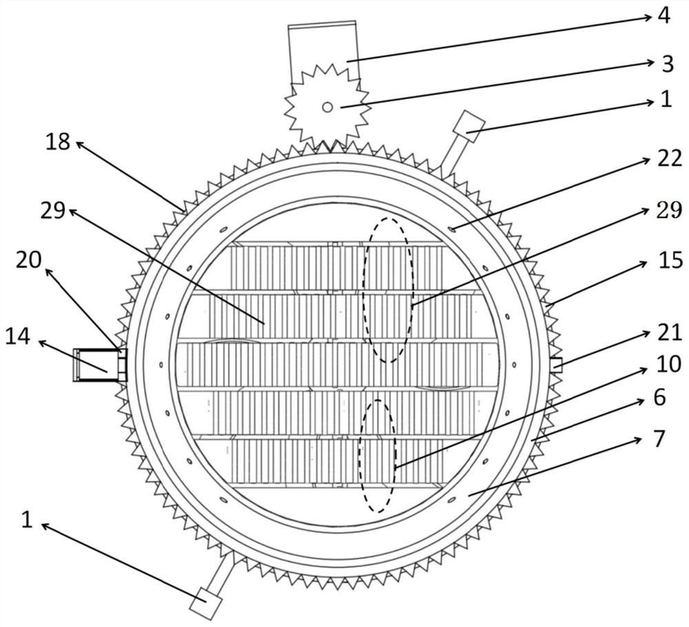
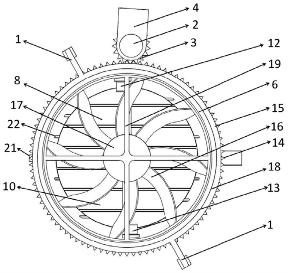
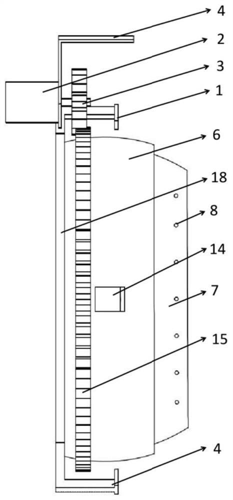
[0035] The present invention is described in further detail below in conjunction with accompanying drawing:

[0036] like Figure 1 to Figure 4 As shown, a swinging air outlet device includes an air channel surface frame 6 and a rotating air channel 7, the air channel surface frame 6 and the rotating air channel 7 are axial through-hole structures, and the rotating air channel 7 is nested in the air channel surface The inner cavity of the frame 6, the two sides of the rotating air duct 7 are rotationally connected with the air duct surface frame 6 through the rotating air duct rotating shaft 21, and the axis of the rotating air duct rotating shaft 21 is perpendicular to the axis of the air duct surface frame 6; The inner cavity surface of the air channel surface frame 6 is a spherical surface. After the two sides of the rotating air channel 7 are connected to the air channel surface frame 6 through the rotary air channel rotating shaft 21, the outer surface of the rotating air...


PUM


Abstract

The invention discloses a swing air outlet device, which adopts an air channel surface frame and a rotating air channel with through-hole structures in the axial direction, and nests the rotating air channel in the inner cavity of the air channel surface frame, and the two sides of the rotating air channel are rotated The shaft of the air duct is rotatably connected with the surface frame of the air duct, and the axis of the shaft of the rotating air duct is perpendicular to the axis of the surface frame of the air duct; The leaf group uses the air duct surface frame and the rotating air duct to form a universal spherical air outlet device that can rotate relative to each other. By adjusting the angle and direction of the air outlet of the rotating air duct, the airflow can reach the designated place with the swing leaf group to achieve personalization. Precise air supply makes the air flow reach the desired place, thus realizing multi-dimensional dynamic air supply, which makes the pulsation of the outlet air flow stronger, increases the turbulence of the indoor air flow, and makes the air output of the air outlet device closer to simulating natural wind, bringing Better blowing experience, improve the comfort of the human body.

Description

technical field [0001] The invention belongs to an air supply device, in particular to a swing air outlet device. Background technique [0002] The air outlet devices of existing air conditioners or other air supply equipment are mostly fixed, and the deflection angle of the air outlet has certain limitations. The air outlet can only be adjusted in the horizontal or vertical direction, and cannot realize 360° multi-dimensional directions. In this way, there will be a dead angle of air supply, and it is impossible to achieve a large wide-angle and a wide range of air supply. At the same time, due to the small change in the angle of the air outlet, the air flow in the room is not uniform, and the air outlet direction is a single vertical and horizontal direction, which is likely to cause concentrated air supply and local overcooling, and most of the air blown out is mechanical wind, which affects people. comfort. Moreover, most of the existing air outlet devices are built-in...

Claims


Application Information

Patent Timeline
Patent Type & Authority Patents(China)
IPC IPC(8): F24F13/14F24F13/10F24F11/79
CPCF24F13/10F24F13/1413F24F2013/1433F24F2013/1446F24F11/79
Inventor 刘小民王加浩田晨晔席光
Owner XI AN JIAOTONG UNIV
Why Eureka
Try Eureka