Cooling device for device cooling and pitch curve calculation method

A cooling device and device technology, applied in complex mathematical operations, heat exchange equipment, lighting and heating equipment, etc., can solve problems such as increasing system complexity, achieve stable transmission, and reduce thermal resistance

Pending Publication Date: 2021-11-19
CHENGDU AERONAUTIC POLYTECHNIC
View PDF0 Cites 0 Cited by
  • Summary
  • Abstract
  • Description
  • Claims
  • Application Information

AI Technical Summary

Problems solved by technology

[0005] 3. The turbulence device and the liquid power pump are usually two independent devices, which increases the complexity of the system

Method used


Image

  • Cooling device for device cooling and pitch curve calculation method
  • Cooling device for device cooling and pitch curve calculation method

Examples


Embodiment Construction

[0023] The specific embodiments of the present invention are described below so that those skilled in the art can understand the present invention, but it should be clear that the present invention is not limited to the scope of the specific embodiments. For those of ordinary skill in the art, as long as various changes Within the spirit and scope of the present invention defined and determined by the appended claims, these changes are obvious, and all inventions and creations using the concept of the present invention are included in the protection list.

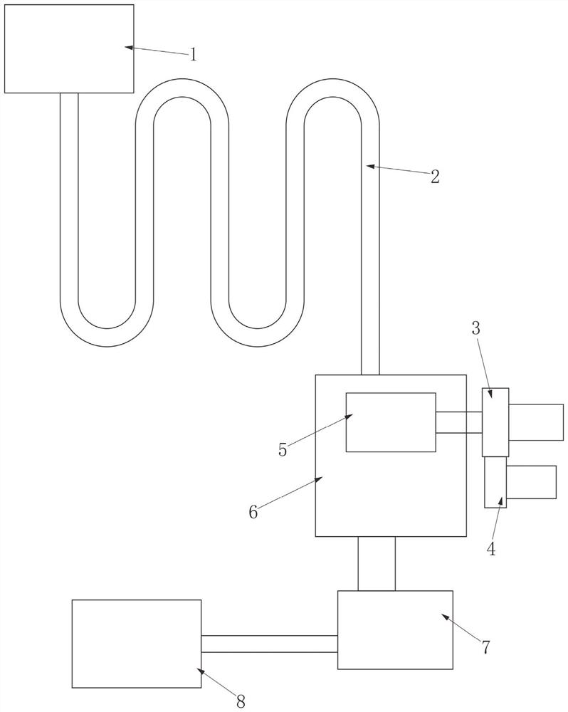
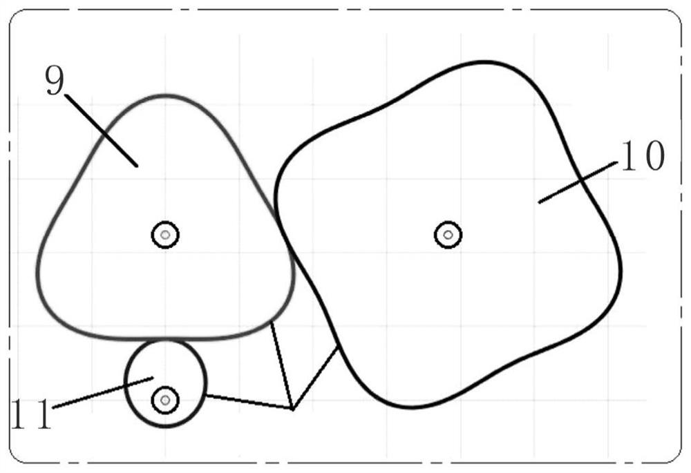
[0024] Such as figure 1 with figure 2 As shown, the cooling device used for device cooling in this solution includes an oscillating cavity, and an impeller is arranged in the oscillating cavity. The impeller is connected to the rotating shaft of the motor through a reduction mechanism. The reducing mechanism includes an elliptical input wheel, and the input wheel is installed on the rotating shaft of the motor. Above, the...


PUM


Abstract

The invention discloses a cooling device for device cooling. The cooling device comprises an oscillation cavity, an impeller is arranged in the oscillation cavity, the impeller is connected with a rotating shaft of a motor through a speed reducing mechanism, the speed reducing mechanism comprises an elliptical input gear, the input gear is installed on the rotating shaft of the motor, the input gear is meshed with a middle gear, and the middle gear is meshed with an output gear. The input gear, the middle gear and the output gear are all installed on the speed reducing mechanism, the middle wheel is a three-order elliptical gear, and the output gear is a four-order elliptical gear. The output gear is connected with the impeller through a transmission shaft. The oscillation cavity is connected with a first external heat exchange device through a liquid channel and connected with a water tank, and the water tank is connected with a second external heat exchange device. The pitch curve calculation method includes the steps S1-S4. According to the cooling device, cooling liquid is output at periodically oscillating pressure and flow; and disturbance of fluid in the fluid channel is increased, turbulent flow is generated to reduce thermal resistance, strong pulsation is generated, and the fluid generates stable turbulent flow.

Description

technical field [0001] The invention relates to the technical field of cooling, in particular to a cooling device for device cooling and a node curve calculation method. Background technique [0002] High heat dissipation power density requires a large flow of coolant, and a large flow of coolant generally requires a large-diameter liquid channel, which has the following problems: [0003] 1. Large-diameter liquid channel bending requires a large bending radius, the heat transfer area per unit volume is small, and the thermal resistance is large; [0004] 2. The liquid flow in the large-diameter liquid channel is generally more laminar flow, which is not easy to generate turbulent flow, and the heat transfer coefficient is low. [0005] 3. The turbulator and the liquid power pump are usually two independent devices, which increases the complexity of the system. [0006] According to the experimental verification, as long as certain hydraulic parameters are matched, self-ex...

Claims


Application Information

Patent Timeline
Patent Type & Authority Applications(China)
IPC IPC(8): F28F13/10G06F17/11
CPCF28F13/10G06F17/11F28F2250/10
Inventor 尹子栋
Owner CHENGDU AERONAUTIC POLYTECHNIC
Why Eureka
Try Eureka