
Piston pin, bushing test piece structure and engine swing wear simulation test tool

A technology of test piece and piston pin, which is applied in the direction of testing wear resistance, measuring devices, instruments, etc., can solve the problems of cumbersome disassembly and assembly process and low utilization rate, and achieve the goal of improving utilization rate, reducing processing cost and saving test cost Effect

Pending Publication Date: 2020-11-10
CHINA NORTH ENGINE INST TIANJIN
View PDF5 Cites 3 Cited by
  • Summary
  • Abstract
  • Description
  • Claims
  • Application Information

AI Technical Summary

Problems solved by technology

[0003] In view of this, the present invention aims to propose a piston pin, bushing test piece structure and engine swing wear simulation test tooling, which solves the technical problem of low utilization rate existing in the existing bushing test piece structure;
[0004] Further solved the technical problem of the cumbersome disassembly and assembly process of the existing test tooling

Method used


Image

  • Piston pin, bushing test piece structure and engine swing wear simulation test tool
  • Piston pin, bushing test piece structure and engine swing wear simulation test tool
  • Piston pin, bushing test piece structure and engine swing wear simulation test tool

Examples


Embodiment Construction

[0026] It should be noted that, in the case of no conflict, the embodiments of the present invention and the features in the embodiments can be combined with each other.

[0027] In describing the present invention, it should be understood that the terms "center", "longitudinal", "transverse", "upper", "lower", "front", "rear", "left", "right", " The orientations or positional relationships indicated by "vertical", "horizontal", "top", "bottom", "inner" and "outer" are based on the orientations or positional relationships shown in the drawings, and are only for the convenience of describing the present invention and Simplified descriptions, rather than indicating or implying that the device or element referred to must have a particular orientation, be constructed and operate in a particular orientation, and thus should not be construed as limiting the invention. In addition, the terms "first", "second", etc. are used for descriptive purposes only, and should not be understood ...


PUM


Abstract

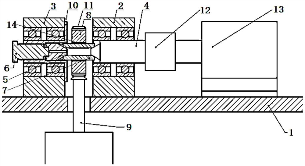
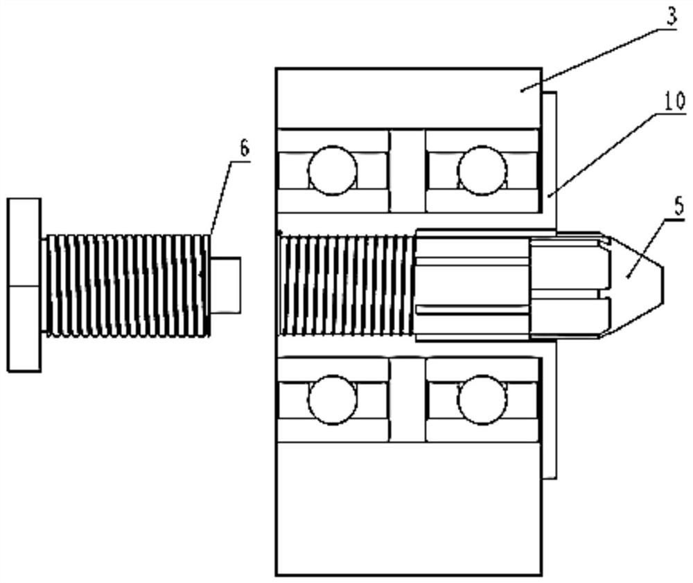
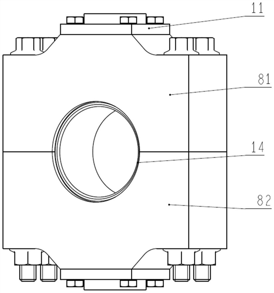
The invention provides a piston pin, a bushing test piece structure and an engine swing abrasion simulation test tool. The engine swing abrasion simulation test tool comprise a first bearing seat, a second bearing seat, a driving motor, a swing type transmission mechanism, a hydraulic cylinder, a driving tip cone shaft, a follow-up tip cone shaft, an adjusting screw and a bushing test piece structure. A bearing of the first bearing pedestal, a bearing of the second bearing pedestal and a circular hole in the bushing test piece structure are coaxially arranged, the bushing test piece structureis arranged between the first bearing pedestal and the second bearing pedestal, the driving motor is connected with the driving tip cone shaft through the swing type transmission mechanism, and the driving tip cone shaft penetrates through the bearing of the second bearing pedestal. According to the piston pin, the bushing test piece structure and the engine swing abrasion simulation test tool, the technical problem that an existing test tool is complex in disassembly and assembly process is solved.

Description

technical field [0001] The invention belongs to the field of engine friction tests, and in particular relates to a structure of a piston pin and a bushing test piece and tooling for an engine swing wear simulation test. Background technique [0002] The friction and wear simulation test of the engine swing friction pair is used to evaluate the tribological performance of the friction pair composed of the engine piston pin and the small end bushing of the connecting rod. The connecting shaft simulates the swinging motion of the small end of the connecting rod through the reciprocating eccentric mechanism or the crank rocker mechanism, and loads the friction pair composed of the piston pin and the connecting rod test part through the hydraulic cylinder. At present, the support method of the test tooling adopts rolling bearings to support both sides of the swing friction pair. The piston pin is installed in cooperation with the two ends of the support shaft through the two ends...

Claims


Application Information

Patent Timeline
IPC IPC(8): G01N3/56G01N3/04G01N3/02
CPCG01N3/56G01N3/04G01N3/02G01N2203/0411
Inventor 张利敏王根全赵志强高丽英袁晓帅强慧刘旭康
Owner CHINA NORTH ENGINE INST TIANJIN
Learn More