
A passenger connection model system and method based on consideration of conventional bus network

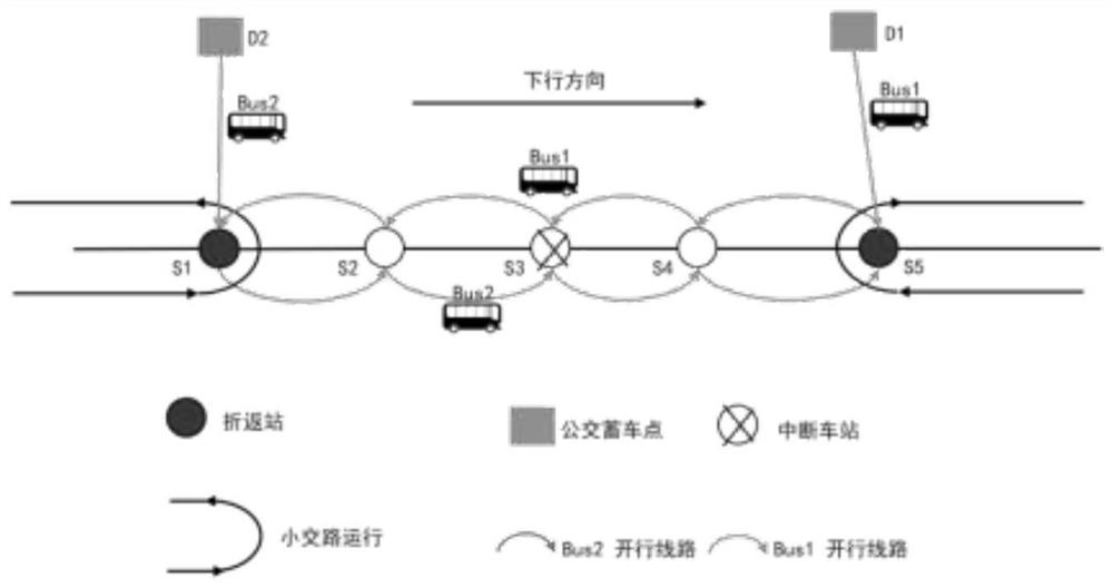
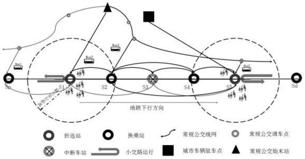
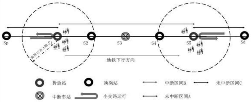
A bus network and model system technology, applied in genetic models, genetic laws, data processing applications, etc., can solve the problems of single supply source of connecting vehicles, waste of vehicle resources, increase passenger travel delays, etc., and reduce passenger delays. The effect of cost, average delay distribution, high connection efficiency

Active Publication Date: 2022-06-28
SOUTHWEST JIAOTONG UNIV
View PDF5 Cites 0 Cited by
  • Summary
  • Abstract
  • Description
  • Claims
  • Application Information

AI Technical Summary

Problems solved by technology

[0004] However, the current connection mode has the following defects: (1) The supply source of connection vehicles is single, and most cities are not equipped with parking spots
Due to the high cost of equipping parking spots, and after planning and construction of emergency bus parking spots in cities equipped with parking spots, there will also be waste of vehicle resources and transport capacity due to long-term emergency incidents, and the cost is too high
(2) During the operation of vehicles, the waste of vehicle capacity is relatively large, and the utilization efficiency of vehicles needs to be improved
Since the vehicles are directly dispatched to the two ends of the turn-back station, most of the passenger demand on the vehicle is the direct demand at the two ends of the turn-back station, including a small number of travel demand vehicles at the middle station. After the stop, no new passengers get on and off the bus, which will cause a waste of vehicle resources.
(3) Calling vehicles and drivers from the bus network without considering the impact of other traffic service levels
When the supply of vehicles and drivers is insufficient, they will be called from the bus network, which will reduce the frequency of regular buses and increase the travel delay of passengers

Method used


Image

  • A passenger connection model system and method based on consideration of conventional bus network
  • A passenger connection model system and method based on consideration of conventional bus network
  • A passenger connection model system and method based on consideration of conventional bus network

Examples


Embodiment Construction

[0045] In order to make the purposes, technical solutions and advantages of the embodiments of the present application more clear, the technical solutions in the embodiments of the present application will be described clearly and completely below with reference to the accompanying drawings in the embodiments of the present application. Obviously, the described embodiments are only It is a part of the embodiments of the present application, but not all of the embodiments. The components of the embodiments of the present application generally described and illustrated in the drawings herein may be arranged and designed in a variety of different configurations. Accordingly, the following detailed description of the embodiments of the application provided in the accompanying drawings is not intended to limit the scope of the application as claimed, but is merely representative of selected embodiments of the application. Based on the embodiments of the present application, all oth...


PUM


Abstract

The invention relates to a passenger connection model and method for subway interruption intervals considering a conventional bus line network, including solving a connection source vehicle selection model and a connection vehicle running path model by using a double-layer genetic algorithm, and outputting an optimal plan. The invention has the advantages of faster response time, lower shunting cost, and no waste of land resources and idle transport capacity compared with only shunting from the parking point by combining the shunting from the conventional bus line network and the parking point. The penalty cost and passenger delay caused by conventional bus shunting are generally smaller than the traditional model; the model is solved by using the double-layer genetic algorithm, the solution speed is fast, and the local optimal solution can be obtained, which has certain feasibility.

Description

technical field [0001] The invention relates to the field of urban traffic planning, in particular to a passenger connection model system and method for a subway interruption interval based on consideration of a conventional bus line network. Background technique [0002] When subway emergencies cause service interruption, there may be problems such as suspension of operation of the entire line, interruption of inter-area services, or overall paralysis of the urban network, resulting in passengers being stranded. At this stage, the emergency bus linkage strategy is adopted, and the shuttle bus is used to complete the evacuation of the stranded passenger flow in the urban rail transit. Some cities have set up urban bus parking points as the supply source for connecting buses. At the design level of emergency bus routes, most cities use conventional bus connections, and the connecting vehicles use conventional bus operation mode when performing passenger evacuation tasks in in...

Claims


Application Information

Patent Timeline
Patent Type & Authority Patents(China)
IPC IPC(8): G06Q50/26G06Q10/06G06N3/12
CPCG06Q50/26G06Q10/067G06Q10/06315G06N3/126
Inventor 刘昱岗郑帅李佳励唐李莹易洪波龚洋杨鸿泰张祖涛
Owner SOUTHWEST JIAOTONG UNIV
Learn More