A drawer type capacitance compensation cabinet

A capacitance compensation cabinet and drawer type technology, applied in pull-out switch cabinets, reactive power compensation, electrical components, etc., can solve problems such as increasing the difficulty of maintenance, improve safety, improve tensile recovery ability, and avoid mutual entangled effect

Active Publication Date: 2022-05-31
XIANGXING ELECTRIC EQUIP
View PDF20 Cites 0 Cited by
  • Summary
  • Abstract
  • Description
  • Claims
  • Application Information

AI Technical Summary

Problems solved by technology

[0004] The above existing technical solutions have the following defects: since the drawer assembly will be powered off when it is pulled out, the components or electronic equipment in the drawer assembly will stop running at this time, and when a fault occurs in the drawer assembly and needs to be repaired, the maintenance personnel It is difficult to quickly find out the fault from all the components and electronic equipment that are out of operation. It is necessary to test each component and electronic equipment one by one, which increases the difficulty of maintenance

Method used


Image

  • A drawer type capacitance compensation cabinet
  • A drawer type capacitance compensation cabinet
  • A drawer type capacitance compensation cabinet

Examples


Embodiment Construction

[0035] The application will be described in further detail below in conjunction with the accompanying drawings.

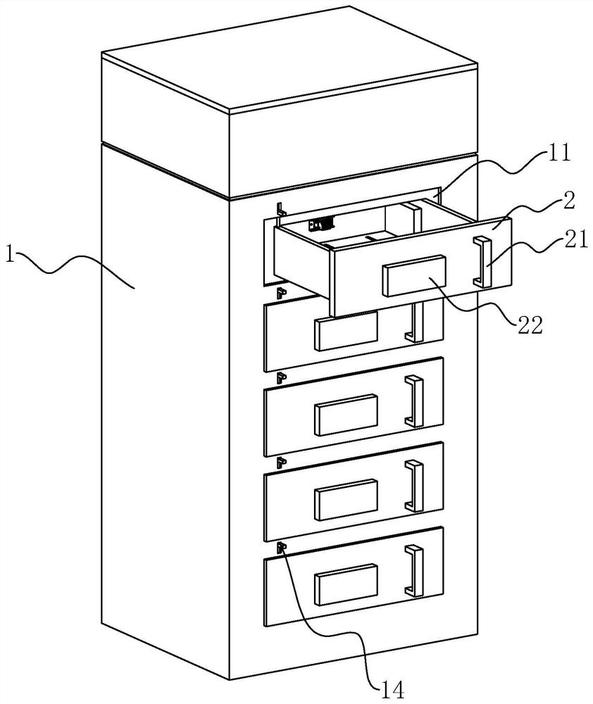
[0036] The present embodiment discloses a drawer-type capacitance compensation cabinet, as shown in FIG.

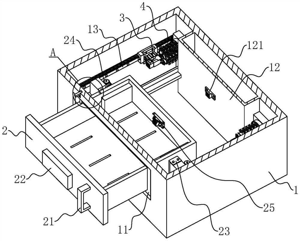
[0037] As shown in Figure 2 and Figure 3, two side walls of the drawer assembly 2 are respectively fixedly connected with a mounting bracket 23, and the mounting bracket 23

[0038] As shown in Figure 2 and Figure 4, the inner walls of the cabinet body 1 on both sides of the corresponding drawer assembly 2 on both sides are fixedly connected with a

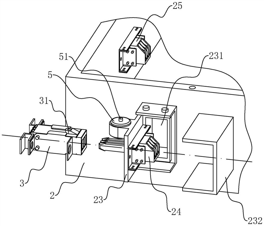
[0039] As shown in FIG. 4 and FIG. 5 , the movable connection mechanism 4 includes a wire 41 and a connection spring 42. One end of the connecting spring 42 is connected to

[0041] As shown in FIG. 4 and FIG. 5, due to the large number of wires 41 connected to the female socket 3, the depth of the constraining groove 431 is set.

[0043] As shown in Figure 2 and Figure 6, the outer side of the cabinet body 1 is slidab...


PUM


Abstract

The application relates to a drawer-type capacitance compensation cabinet, which includes a cabinet body, and a plurality of drawer openings are arranged on the cabinet body, and a drawer assembly is slidingly arranged in the drawer opening; a male plug is arranged on the drawer assembly, so that A female socket is slidingly arranged in the drawing opening; a movable connection mechanism is arranged between the female socket and the cabinet body; a locking device is arranged between the male plug-in and the female socket. When the drawer assembly is pulled out, it drives the female socket to move outward synchronously, so that the components and electronic equipment in the drawer assembly are still in operation, so that the fault in the drawer assembly can be observed clearly; when maintenance is required, then The male plug and the female socket are unlocked by the locking device, and the male plug and the female socket are separated from each other, so that the drawer assembly is powered off, and the safety during maintenance is improved.

Description

A drawer type capacitor compensation cabinet technical field [0001] The application relates to the technical field of capacitance compensation cabinets, in particular to a drawer type capacitance compensation cabinet. Background technique [0002] Most of the load types in the power system belong to inductive loads, and electricity companies generally use electricity widely. Electronic equipment to make the grid power factor low. Lower power factor reduces equipment utilization, increases power supply investment, and costs It harms the voltage quality, reduces the service life of the equipment, and greatly increases the line loss. Therefore, by connecting a capacitor in the power system The compensation cabinet can balance the inductive load and improve the power factor to improve the utilization rate of the equipment. [0003] In the prior art, the Chinese patent document with the authorization announcement number of CN104037637B discloses a drawer capacitor Compens...

Claims


Application Information

Patent Timeline
Patent Type & Authority Patents(China)
IPC IPC(8): H02B11/133H02B1/20H02H7/22
CPCH02B11/133H02B1/20H02H7/22Y02E40/30
Inventor 余东博江君华
Owner XIANGXING ELECTRIC EQUIP
Why Eureka
Try Eureka