
Fly trap for food processing

A technology of food processing and fly killers, which is applied to the application, devices for catching or killing insects, animal husbandry, etc. It can solve the problems of poor fly killing efficiency, inability to catch flies, unfavorable large-scale use, etc.

Inactive Publication Date: 2020-11-13
XUZHOU LISTON IND DESIGN CO LTD
View PDF2 Cites 2 Cited by
  • Summary
  • Abstract
  • Description
  • Claims
  • Application Information

AI Technical Summary

Problems solved by technology

[0002] At present, during manual food processing, flies need to be cleaned frequently, because flies like to crawl and look for food in rotten objects, garbage bins, etc., and it is very easy to carry a large number of germs. If preventive measures are not taken during manual food processing, it is very easy Let flies spread diseases. During manual food processing, it is necessary to avoid using chemicals to clean up flies to ensure food safety. Therefore, most of the existing fly killing devices use trapping methods, but traditional trapping devices use food to lure flies. , using the characteristics that flies cannot be vertically lifted, to hunt and kill, but it is impossible to concentrate the bodies of trapping and killing flies. The distribution of fly bodies is messy, which causes great inconvenience to personnel cleaning
Some devices use trapping and fan suction to kill flies. The fly is sucked from top to bottom. The actual use of the fly killing efficiency is too poor. The suction of the fan is small, and the flies cannot be caught. The suction is too large, and the flies cannot be caught. Moreover, it needs a strong irritating bait, it is used in places with many flies, and it is not suitable for food processing sites
[0003] The notification number CN204292049U discloses a fly trap, which includes an opaque base, an isolation net cover and a transparent outer cover. The base is a cylindrical structure with a circular groove on the base. The outer surface is provided with a number of fly inlets along the circumference, and the through holes communicate with the fly inlets. The isolation net cover is funnel-shaped and has mesh holes on the isolation net cover. An escape pipe is provided outside the upper opening of the isolation net cover. The edge of the lower end of the opening extends outward to form a crimping flange, the bottom surface of the crimping flange is in contact with the bottom of the circular groove, the outer diameter of the crimping flange matches the diameter of the circular groove, and the crimping flange The thickness is less than the depth of the circular groove. The outer cover is covered outside the isolation net and is in contact with the surface of the crimping flange. The outer diameter of the bottom of the outer cover matches the diameter of the circular groove. The device is distributed on the isolation net after the flies die Four weeks, it is impossible to carry out a centralized treatment of the corpses, which causes great inconvenience to personnel cleaning
[0004] The notification number CN206150272U discloses a fly sight-guided killing device, including a tube body, and a high-voltage insecticidal system; the high-voltage insecticidal system includes a booster system, and an array of insecticidal electrodes connected to the booster system; the tube body is provided with The opening is used as a fly inlet for flies to fly in; an insecticidal electrode array is arranged in the tube body, and part or all of the insecticidal electrode array is located above the fly inlet; the tube body is provided with a light-transmitting port at least above the middle of the insecticidal electrode array , and a transparent window for blocking flies is provided at the light-transmitting port. This device kills flies through electric current. It needs to be connected to the power supply in the process of use, which is relatively complicated, and it is not simple and fast enough to use, which is not conducive to large-scale use.

Method used


Image

  • Fly trap for food processing
  • Fly trap for food processing
  • Fly trap for food processing

Examples


Embodiment Construction

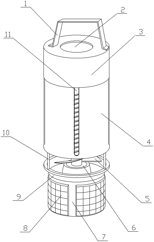
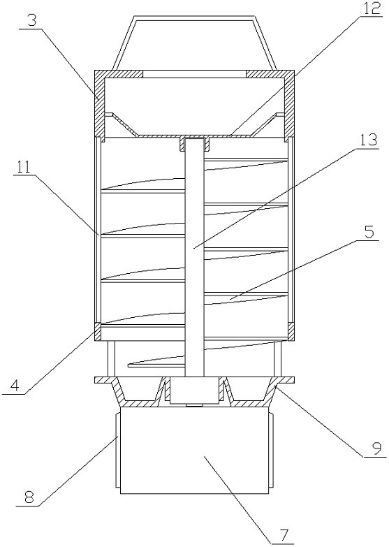
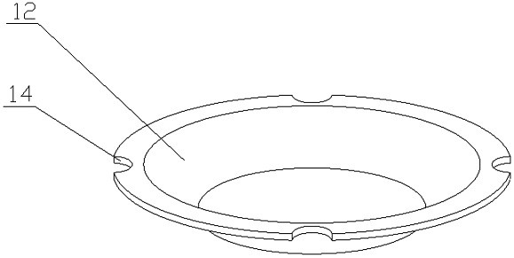
[0016] A fly killer for food processing of the present invention is achieved in the following way: a fly killer for food processing of the present invention consists of a fixed frame (1), a built-in lamp (2), an upper box (3), a lower box (4 ), spiral blade (5), drive motor (6), battery (7), photovoltaic panel (8), bait plate (9), fixed rod (10), light-transmitting film (11), inner partition (12) , a drive rod (13) and a catch hole (14), the bait tray (9) is placed on the top of the battery (7), and a plurality of photovoltaic panels (8) are placed on the outer wall of the battery (7). An annular groove is clamped on the bait pan (9), the edge of the bait pan (9) extends to a supporting platform, one end of a plurality of fixed rods (10) is placed on the edge of the bait pan (9) at an equal angle, and the lower box (4 ) placed on the other end of the fixing rod (10), the lower box (4) is distributed with a plurality of through grooves along the circumferential direction, the t...


PUM


Abstract

The invention relates to a fly trap for food processing, and discloses a fly killing device which can be easily added with a bait, can match the structure of a bait tray, force a fly to fly and to enter a spiral blade, and then lure the fly from the notch into an upper box body by a built-in lamp in the upper box body to catch the fly. The fly trap is characterized in that: the bait tray is arranged at the top of a storage battery, a plurality of photovoltaic panels are arranged on the outer side wall of the storage battery, an annular groove is clamped on the bait tray, the edge of the bait tray extends to form a phase difference support table, one ends of a plurality of fixing rods are arranged at the edge of the bait tray at equal angles, a lower box body is arranged at the other ends of the fixing rods, a plurality of through grooves are distributed in the lower box body in the circumferential direction, the through grooves penetrate through the lower box body along the axis, a plurality of light-transmitting films are correspondingly embedded in the through grooves, the upper box body is detachably arranged at the top of the lower box body, and an inner partition plate is arranged in the upper box body and attached to the inner wall of the inner box body.

Description

technical field [0001] The invention relates to a fly killer for food processing, relates to a fly killer for cleaning flies during manual food processing, and belongs to the field of food processing. In particular, it relates to a structure that can facilitate the addition of bait and can cooperate with the bait tray to force the flies to fly and enter between the spiral blades, and then use the built-in lamp in the upper box to lure the flies into the upper box from the gap to catch the flies fly killer. Background technique [0002] At present, during manual food processing, flies need to be cleaned frequently, because flies like to crawl and look for food in rotten objects, garbage bins, etc., and it is very easy to carry a large number of germs. If preventive measures are not taken during manual food processing, it is very easy Let flies spread diseases. During manual food processing, it is necessary to avoid using chemicals to clean up flies to ensure food safety. The...

Claims


Application Information

Patent Timeline
Patent Type & Authority Applications(China)
IPC IPC(8): A01M1/02A01M1/06
CPCA01M1/02A01M1/06
Inventor 不公告发明人
Owner XUZHOU LISTON IND DESIGN CO LTD
Learn More