Solid building waste crushing and recycling device

A construction waste and recycling device technology, applied in construction waste recycling, solid waste removal, solid separation and other directions, can solve the problems of affecting recycling, incomplete waste crushing, etc. The effect of start-stop operation

Inactive Publication Date: 2020-11-13
深圳市汇利德邦环保科技有限公司
View PDF9 Cites 13 Cited by
  • Summary
  • Abstract
  • Description
  • Claims
  • Application Information

AI Technical Summary

Problems solved by technology

[0003] Most of the existing crushing and recycling devices can only process construction waste once, which often leads to incomplete crushing of waste, affecting subsequent recycling, and there are certain defects in use

Method used


Image

  • Solid building waste crushing and recycling device
  • Solid building waste crushing and recycling device
  • Solid building waste crushing and recycling device

Examples


Embodiment 1

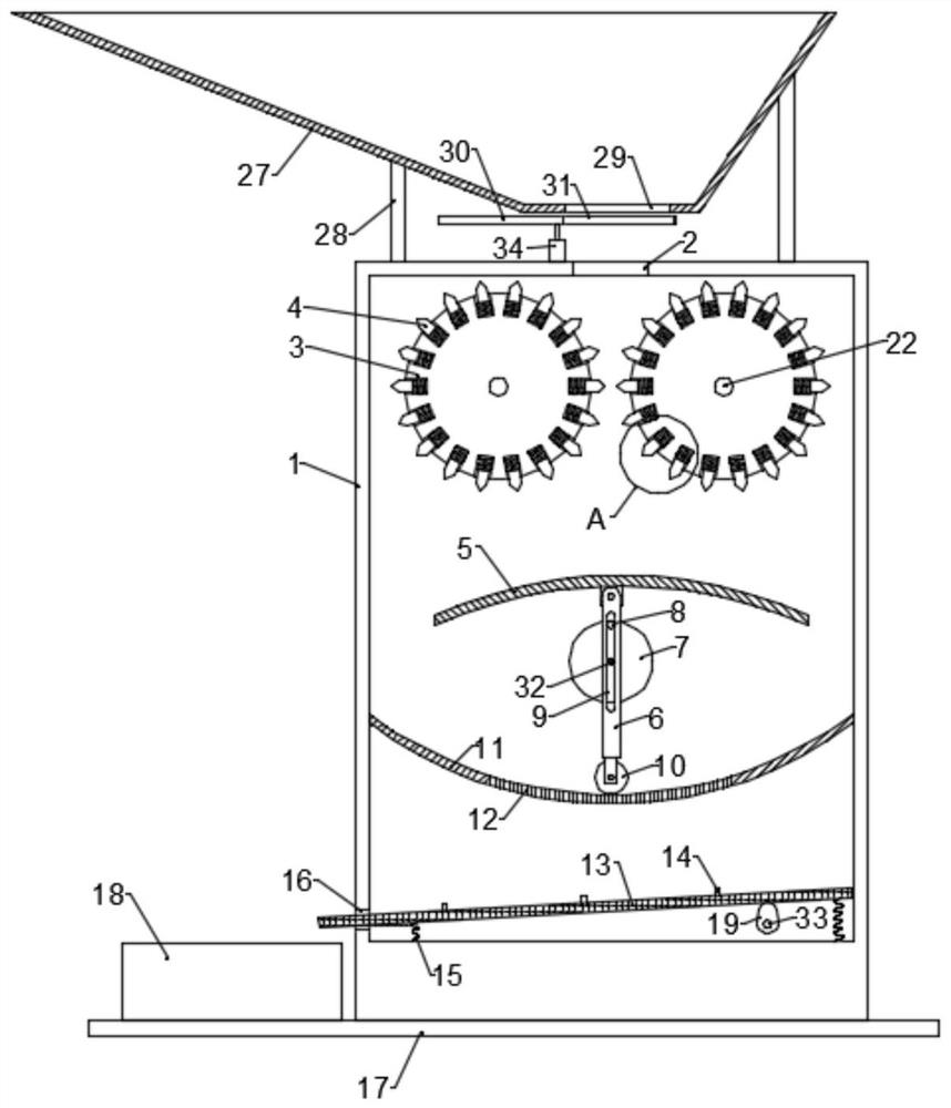
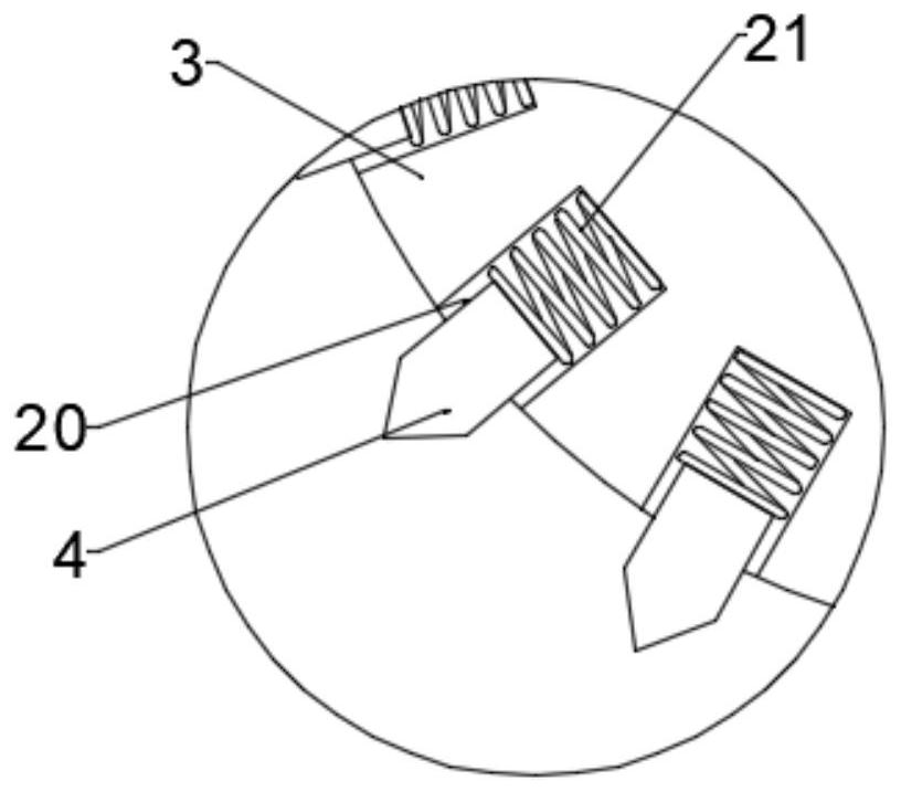
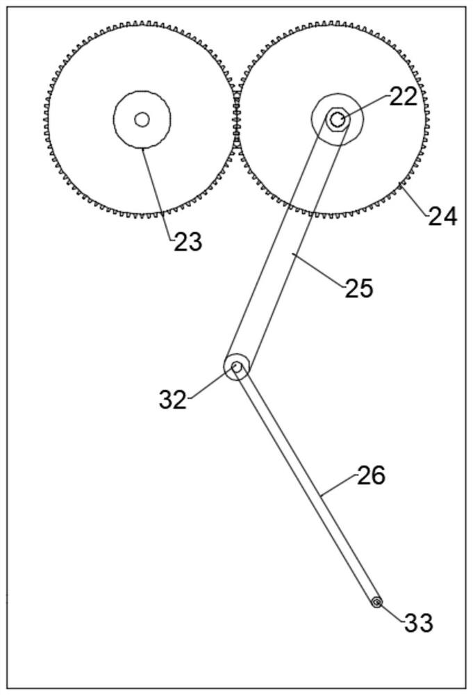
[0023] see Figure 1~4 , in an embodiment of the present invention, a solid construction waste crushing and recycling device includes a base 17 and a main box 1 fixed to the base 17; the top shell wall of the main box 1 is provided with a feed port 2, and Two crushing rollers 3 arranged symmetrically are arranged above the inner cavity of the casing 1. The crushing rollers 3 are connected to the main casing 1 through the rotation of the first rotating shaft 22. The crushing rollers 3 are evenly distributed with crushing teeth 4. The two crushing rollers The gap between 3 is facing the feed inlet 2, and the middle part of the inner cavity of the main box body 1 is fixed with a deflector 5, and the lower part of the deflector 5 is provided with an arc-shaped pressure plate 11 at intervals, and a blanking hole is opened on the pressure plate 11 12. The central position of the bottom of the deflector 5 is rotatably connected to a swing frame 6, and the bottom of the swing frame 6 ...

Embodiment 2

[0031] This embodiment expands the functions on the basis of Embodiment 1, specifically:

[0032] The top of the main box body 1 is also provided with a material frame 27, the material frame 27 is fixed on the top of the main box body 1 by a bracket 28, and the bottom shell wall of the material frame 27 is provided with a discharge port facing the feed port 2 29. It can facilitate the placement of waste.

[0033] Further, the bottom of the material frame 27 is also fitted with a disk 30, one side of the disk 30 is provided with a through hole 31 matching the discharge port 29, and the top of the main box 1 is installed with a second Motor 34, the output end of the second motor 34 is connected with disc 30, during work, drives disc 30 to rotate by second motor 34, and when through hole 31 rotates to the position relative to discharge port 29, waste passes through material The frame 27 falls into the main box body 1, and when the through hole 31 rotates to a position staggered fr...


PUM


Abstract

The invention discloses a solid building waste crushing and recycling device. The solid building waste crushing and recycling device comprises a base and a main box body fixed to the base. A feeding port is formed in the shell wall of the top of the main box body, two symmetrically-arranged crushing rollers are arranged at the upper part of an inner cavity of the main box body, and the crushing rollers are rotationally connected with the main box body through first rotating shafts. Crushing teeth are evenly distributed on the crushing rollers, a gap between the two crushing rollers directly faces the feeding port, and a flow guide plate is fixed to the middle of the inner cavity of the main box body. An arc-shaped pressing plate is arranged below the flow guide plate in a spaced mode, anda material falling hole is formed in the pressing plate. A swing frame is rotationally connected to the center of the bottom of the flow guide plate, a pressing roller is installed at the bottom of the swing frame, and the rotating radius of the pressing roller is the same as the radius of the pressing plate. A strip-shaped hole is formed in the swing frame in the length direction of the swing frame, and a rotary disc is arranged on the rear side of the swing frame. The crushing degree of waste is improved, and the crushing effect can be effectively guaranteed when the pressing rollers crush the waste.

Description

technical field [0001] The invention relates to the field of building construction, in particular to a crushing and recycling device for solid construction waste. Background technique [0002] A large amount of waste will be generated in the process of building construction, which will pollute the environment if it is not disposed of in time. Generally speaking, the treatment of buildings is mostly achieved by crushing. [0003] Most of the existing crushing and recycling devices can only process construction waste once, which often leads to incomplete crushing of waste, which affects subsequent recycling, and has certain defects in use. Contents of the invention [0004] The object of the present invention is to provide a crushing and recycling device for solid construction waste to solve the problems raised in the above-mentioned background technology. [0005] To achieve the above object, the present invention provides the following technical solutions: [0006] A cru...

Claims


Application Information

Patent Timeline
Patent Type & Authority Applications(China)
IPC IPC(8): B02C4/08B02C4/12B02C4/28B02C4/30B02C4/42B02C23/02B02C23/10B07B1/28B07B1/42B09B3/00B09B5/00
CPCB02C4/08B02C4/12B02C4/286B02C4/30B02C4/42B02C23/02B02C23/10B07B1/28B07B1/42B09B3/00B09B5/00Y02W30/58
Inventor 吴裕明朱金龙
Owner 深圳市汇利德邦环保科技有限公司
Why Eureka
Try Eureka