Knife handle water transfer printing device for knife making
A technology of water transfer printing and knife handle, applied in transfer printing, rotary printing machine, printing and other directions, can solve the problems of affecting the effect of the knife handle, large buoyancy of the knife handle, labor-consuming and other problems, saving labor, simple operation, guaranteeing effect of effect
- Summary
- Abstract
- Description
- Claims
- Application Information
AI Technical Summary
Problems solved by technology
Method used
Image
Examples
Embodiment 1
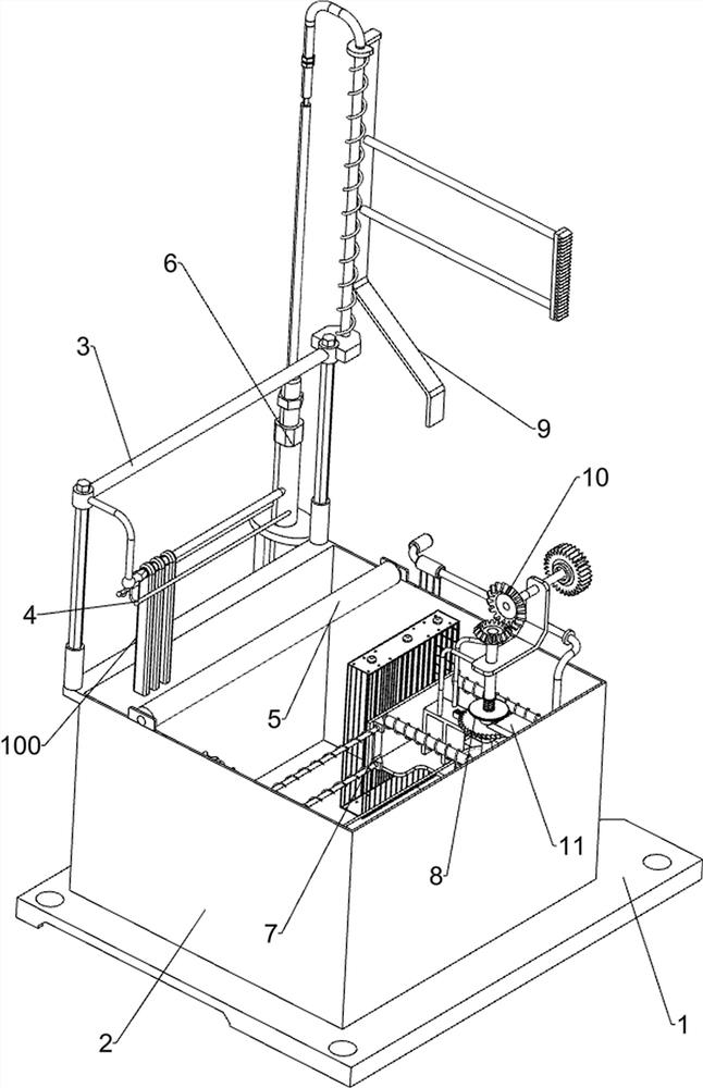
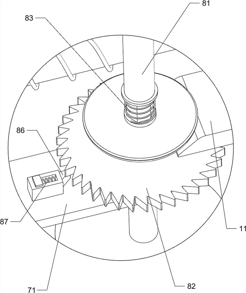
[0027] A knife handle water transfer printing device for knife making, such as Figure 1-4 As shown, it includes a base 1, a liquid storage frame 2, a first sliding frame 3, a limit rod 4 and a material spacer 5. The top of the base 1 is connected with a liquid storage frame 2, and the top of the liquid storage frame 2 is sliding on the left. The first sliding frame 3 is connected, and the left and right sides of the bottom of the first sliding frame 3 are connected with limit rods 4, and the left side of the top of the liquid storage frame 2 is connected with a spacer 5, and also includes a lifting assembly 6, a collection assembly 7 and a pusher assembly. Material assembly 8, a lifting assembly 6 is provided between the base 1 and the first sliding frame 3, a collection assembly 7 is provided in the liquid storage frame 2, and a pushing assembly 8 is provided on the collection assembly 7.
[0028] Lifting assembly 6 comprises cylinder 61, second sliding frame 62 and compress...
Embodiment 2
[0033] On the basis of Example 1, such as image 3 As shown, a moving assembly 9 is also included. The moving assembly 9 includes a guide plate 91 and a tension spring 92. The second sliding frame 62 is connected with a guide plate 91. The guide plate 91 cooperates with the sliding rod 77. The first mounting bracket 71 A tension spring 92 is connected with the liquid storage frame 2 .
[0034]When the second sliding frame 62 moves up and down, it will drive the guide plate 91 to move up and down together. When the first sliding frame 3 moves down to the limit, the guide plate 91 also moves to contact with the sliding rod 77, and the compression spring 63 is compressed. When the second sliding frame 62 continues to move downwards and pulls the sliding bar 77 to move to the left, the sliding bar 77 moves to drive the first mounting frame 71 to move, and the extension spring 92 is stretched. After the second sliding frame 62 resets, it will Under the action of the spring 92, the...
Embodiment 3
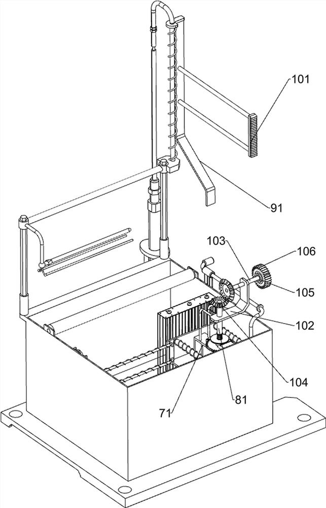
[0036] On the basis of Example 2, such as Figure 5 As shown, a rotating assembly 10 is also included, and the rotating assembly 10 includes a driving rack 101, a second mounting bracket 102, a rotating shaft 103, a bevel gear 104, a one-way clutch 105 and a driving gear 106, and the right side of the guide plate 91 is connected with a driving Rack 101, the first mounting frame 71 is connected with the second mounting frame 102, the second mounting frame 102 is connected with the rotating shaft 103, the rear part of the rotating shaft 103 is connected with the one-way clutch 105, and the one-way clutch 105 is connected with the drive The gear 106, the driving rack 101 will mesh with the driving gear 106, the top of the shaft 81 and the front of the rotating shaft 103 are connected with a bevel gear 104, and the two bevel gears 104 are meshed with each other.
[0037] Guide plate 91 drives drive rack 101 to move up and down together when moving up and down, and when drive rack ...
PUM
 Abstract
Description
Claims
Application Information
 - R&D Engineer
- R&D Manager
- IP Professional
- Industry Leading Data Capabilities
- Powerful AI technology
- Patent DNA Extraction
Browse by: Latest US Patents, China's latest patents, Technical Efficacy Thesaurus, Application Domain, Technology Topic, Popular Technical Reports.
© 2024 PatSnap. All rights reserved.Legal|Privacy policy|Modern Slavery Act Transparency Statement|Sitemap|About US| Contact US: help@patsnap.com


