Filling head following lifting mechanism and working method thereof

A lifting mechanism and filling head technology, applied in packaging, packaging protection, transportation and packaging, etc., can solve the problems of prolonging filling time and reducing work efficiency, and achieve the effect of improving work efficiency and shortening filling time.

Pending Publication Date: 2020-11-13
JIANGSU JINWANG PACKING SCI TECH CO LTD
View PDF0 Cites 3 Cited by
  • Summary
  • Abstract
  • Description
  • Claims
  • Application Information

AI Technical Summary

Problems solved by technology

[0003] The purpose of the present invention is to provide a filling head following the lifting mechanism and its working method to solve the technical problems in the prior art that the packaging material stops for filling, prolongs the filling time and reduces work efficiency

Method used


Image

  • Filling head following lifting mechanism and working method thereof
  • Filling head following lifting mechanism and working method thereof
  • Filling head following lifting mechanism and working method thereof

Examples


Embodiment 1

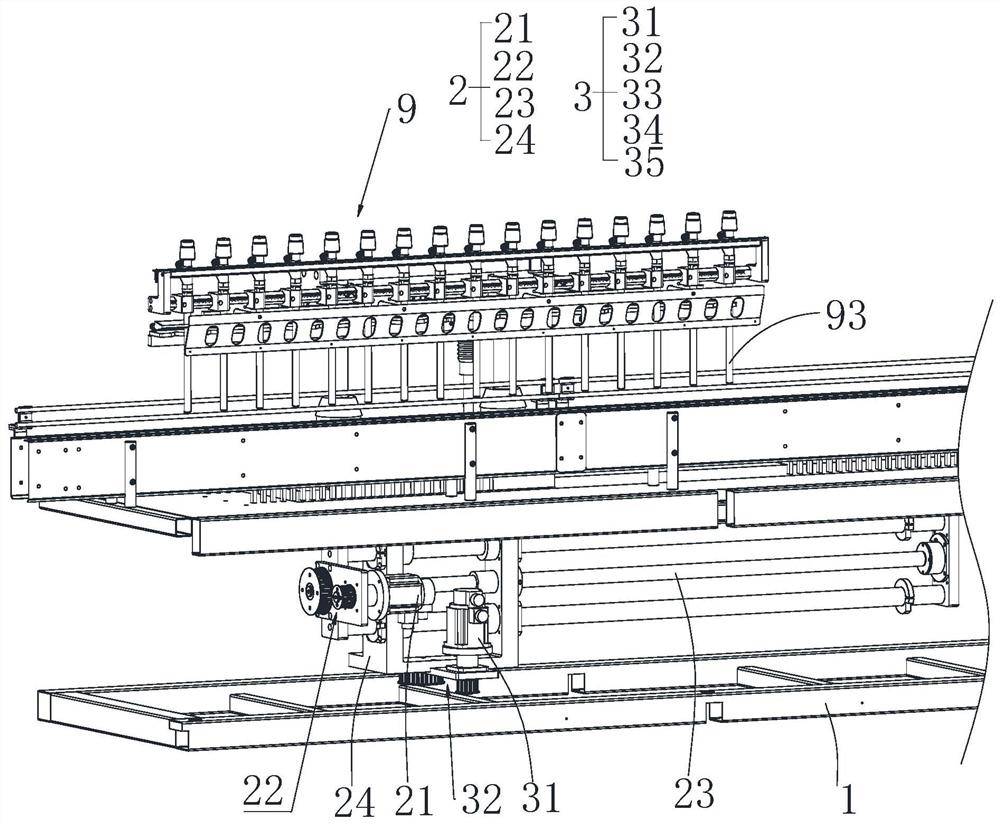
[0024] Such as Figure 1 to Figure 3 As shown, this embodiment provides a filling head following lifting mechanism, including: a support 1 , a traction mechanism 2 disposed on the support 1 , and a lifting mechanism 3 disposed on the traction mechanism 2 . Specifically, the traction mechanism 2 is suitable for driving the lifting mechanism 3 to move synchronously with the packaging material, so that when the lifting mechanism 3 moves, the lifting mechanism 3 is suitable for driving the feeding nozzle mechanism 9 to descend into the packaging material for filling.

[0025] Specifically, in this embodiment, the traction mechanism 2 includes: a first driving member 21 , a first transmission member 22 , a first screw rod 23 and a first moving seat 24 . The first moving seat 24 is screwed on the first screw mandrel 23 , and the lifting mechanism 3 is installed on the first moving seat 24 . When the traction mechanism 2 is in use, start the first driving member 21, drive the first ...

Embodiment 2

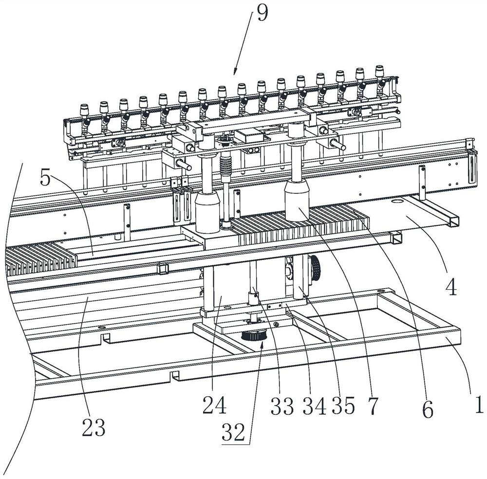
[0040] Such as figure 2 As shown, this embodiment provides a working method in which the filling head follows the lifting mechanism, the lifting mechanism 3 is driven by the traction mechanism 2 to follow the packaging material, and while the lifting mechanism 3 is moving, the feeding nozzle is driven by the lifting mechanism 3 Mechanism 9 descends to filling in the packaging material.

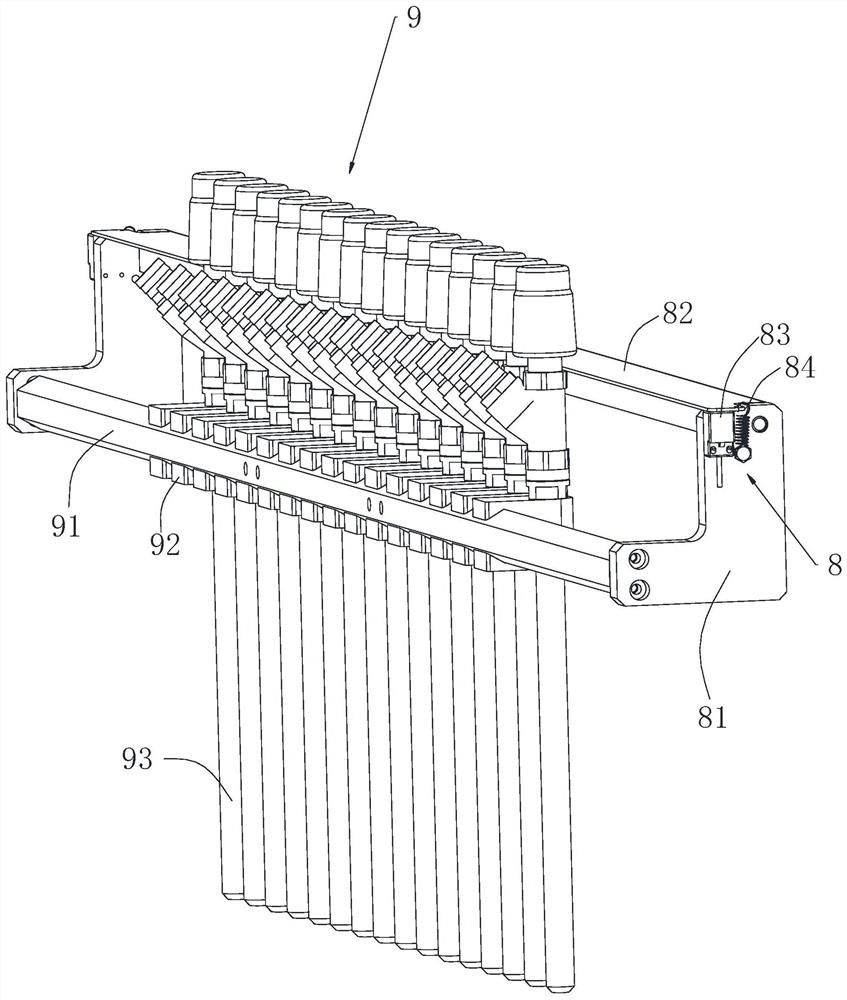
[0041] To sum up, while the lifting mechanism 3 is driven by the traction mechanism 2 to move with the packaging material, the lowering nozzle 93 mechanism 9 is driven by the lifting mechanism 3 to drop into the packaging material for filling, thereby realizing the process of conveying the packaging material. Filling can be completed, the packaging material does not need to be stopped, the filling time is shortened, and the work efficiency is improved; the guide sleeve 7 adapted to the guide post 35 is arranged on the installation plate, so that the guide post 35 is more stable when moving up...


PUM


Abstract

The invention belongs to the technical field of filling machines, and particularly relates to a filling head following lifting mechanism and a working method thereof. The mechanism comprises a bracket, a traction mechanism arranged on the bracket and a lifting mechanism arranged on the traction mechanism. The traction mechanism is suitable for driving the lifting mechanism to move synchronously with packaging materials, and while the lifting mechanism moves, the lifting mechanism is suitable for driving a feeding nozzle mechanism to descend into the packaging materials for filling. The fillinghead following lifting mechanism uses the traction mechanism to drive the lifting mechanism to follow the movement of the packaging materials, and at the same time, the feeding nozzle mechanism is driven by the lifting mechanism to lower into the packaging materials for filling. Therefore, the filling can be completed in the process of conveying the packaging materials by a packaging material conveyor chain, the packaging materials do not need to be stopped, the filling time is shortened and the work efficiency is improved.

Description

technical field [0001] The invention belongs to the field of filling machines, and in particular relates to a filling head following lifting mechanism and a working method thereof. Background technique [0002] When the existing filling machine is filling the product, the packaging material is first conveyed to the discharge nozzle by the conveying line, and then stops, and the lifting mechanism takes the discharge nozzle down to the packaging material and starts to inject liquid, and the filling is completed. Finally, the lifting mechanism will bring the feeding nozzle up, and finally remove the packaging material; this filling method that requires the packaging material to stop and fill prolongs the filling time and reduces work efficiency; at the same time, the existing filling There is a buffer machine between the loading machine and the capping machine, which is used to place the packaging materials to be filled. Contents of the invention [0003] The purpose of the ...

Claims


Application Information

Patent Timeline
Patent Type & Authority Applications(China)
IPC IPC(8): B65B39/12B65B57/00
CPCB65B39/12B65B57/005
Inventor 房国荣张帅司马铃
Owner JIANGSU JINWANG PACKING SCI TECH CO LTD
Why Eureka
Try Eureka