
Positive pulse generator

A generator and positive pulse technology, applied in the field of positive pulse generators, can solve problems such as poor pulse effect

Active Publication Date: 2020-11-13
CHINA UNIV OF PETROLEUM (BEIJING) +1
View PDF8 Cites 0 Cited by
  • Summary
  • Abstract
  • Description
  • Claims
  • Application Information

AI Technical Summary

Problems solved by technology

[0004] Therefore, in the existing positive pulse generator, the pulse is only generated through the pulse valve with one end closed, and the pulse effect is not good.

Method used


Image

  • Positive pulse generator
  • Positive pulse generator
  • Positive pulse generator

Examples


Embodiment Construction

[0039] In order to make the purpose, technical solutions and advantages of the embodiments of the present invention clearer, the technical solutions in the embodiments of the present invention will be clearly and completely described below in conjunction with the drawings in the embodiments of the present invention. Obviously, the described embodiments It is a part of embodiments of the present invention, but not all embodiments.

[0040] Based on the embodiments of the present invention, all other embodiments obtained by persons of ordinary skill in the art without making creative efforts belong to the protection scope of the present invention. In the case of no conflict, the following embodiments and features in the embodiments can be combined with each other.

[0041] In describing the present invention, it should be understood that the terms "center", "longitudinal", "transverse", "length", "width", "thickness", "upper", "lower", "front", " Back", "Left", "Right", "Vertic...


PUM


Abstract

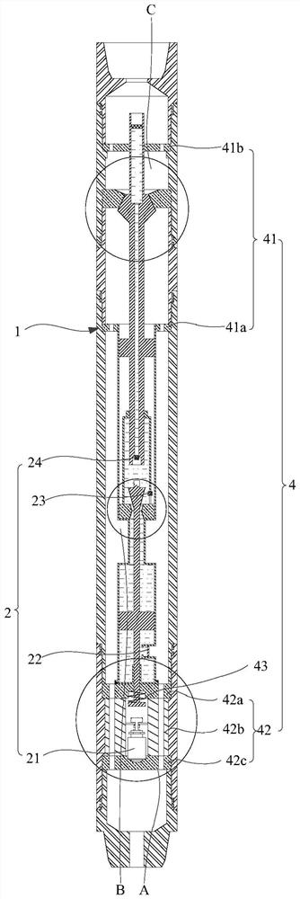
The invention provides a positive pulse generator. The positive pulse generator comprises a shell, an electromagnetic valve assembly, a pressure transmission assembly, a supporting and guiding assembly and pulse conversion assemblies, wherein the electromagnetic valve assembly, the pressure transmission assembly and the pulse conversion assemblies are all located in the shell and sequentially arranged in the axial direction of the shell, and the shell is connected with the pressure transmission assembly through the supporting and guiding assembly; the electromagnetic valve assembly comprises afirst electromagnetic valve used for driving part of components in the pressure transmission assembly to move, so that pressure liquid in the pressure transmission assembly drives the pulse conversion assemblies to generate pulses; the pulse conversion assemblies comprise the first pulse conversion assembly and the second pulse conversion assembly, the first pulse conversion assembly is connectedwith the pressure transmission assembly, and the second pulse conversion assembly is located in the first pulse conversion assembly and is in sliding fit with the first pulse conversion assembly. Thepositive pulse generator provided by the invention has high stability.

Description

technical field [0001] The invention relates to the technical field of oil field development, in particular to a positive pulse generator. Background technique [0002] Nowadays, in the process of oil exploration, measurement while drilling (Measure While Drilling, MWD) and logging while drilling (Logging While Drilling, LWD) technologies are widely used. MWD is a technology that installs measurement tools at appropriate positions in the drilling tool to measure downhole information in real time while drilling; LWD requires the use of more complex measurement-while-drilling tools, which also have more diverse It also has greater advantages in obtaining downhole information and evaluating formations. In actual drilling, the data transmission of MWD and LWD is mainly divided into two types: wireless transmission and wired transmission according to the different transmission channels. The wireless transmission method is widely used, and among the wireless transmission methods...

Claims


Application Information

Patent Timeline
Patent Type & Authority Applications(China)
IPC IPC(8): E21B47/24
Inventor 宋考平付洪涛蒋声东郭春萍李云峰
Owner CHINA UNIV OF PETROLEUM (BEIJING)
Learn More