A thrust sleeve compensator for straight pipe and its implementation method
A sleeve compensator and thrust technology, which is applied to expansion compensation devices, pipe components, flange connections and other directions for pipelines, can solve the problems of no thermal insulation structure, general thermal insulation effect, and difficulty in fitting the pipeline, and achieve reliable performance. Stable compensation performance, small resistance, the effect of reducing pressure
- Summary
- Abstract
- Description
- Claims
- Application Information
AI Technical Summary
Problems solved by technology
Method used
Image
Examples
Embodiment 1
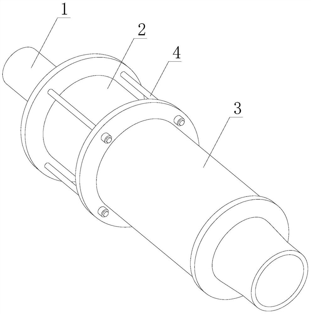
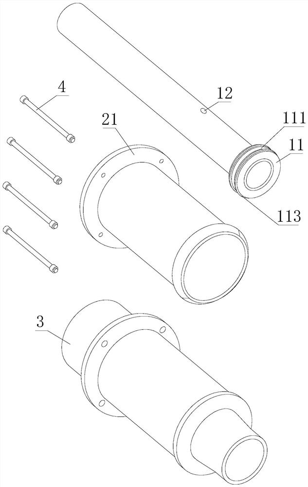
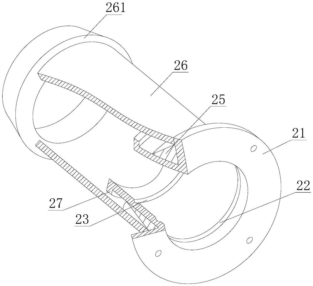
[0038] see Figure 1-Figure 2, a thrust sleeve compensator for straight pipes, comprising a telescopic core pipe 1, a positioning sleeve 2 and an outer casing 3, one end of the telescopic core pipe 1 is connected to a limiting sleeve 11, and the limiting sleeve 11 is provided with a groove 111, the groove 111 is filled with a first sealing filler 112, the side wall of the limit sleeve 11 is connected with a first sealing ring 113, and the first sealing ring 113 is connected to the inner wall of the outer sleeve The telescopic core tube 1 on the side of the position sleeve 11 is symmetrically provided with a first through hole 12, and the end of the telescopic core tube 1 close to the limit sleeve 11 penetrates the positioning sleeve 2 and the outer sleeve 3 in sequence, and the telescopic core tube 1 is placed in the first through hole 12. A second sealing packing 13 is arranged between the ring plate 27 and the second ring plate 35, a second sealing ring 14 is arranged betwee...
Embodiment approach
[0041] In order to better demonstrate the implementation process of the thrust sleeve compensator for straight pipes, the present embodiment now proposes a thrust sleeve compensator for straight pipes and an implementation method thereof, including the following steps:
[0042] Step 1: During processing, the outer sleeve 32 and the outer sleeve 3 are filled with thermal insulation cotton, the outer sleeve 32 is connected to the outside of the thermal insulation cotton, and the positioning sleeve 2 and the inner sleeve 26 are also filled with thermal insulation cotton. Insulation cotton is used for heat preservation, and the sealing conditions between the outer sleeve 32 and the outer sleeve 3 are not required to be too high;
[0043] Step 2: The long screw 4 penetrates the first flange 21 and the second flange 31, connects the positioning sleeve 2 and the outer sleeve 3, and locks the position of the positioning sleeve 2 and the outer sleeve 3 through the nut, and the long scre...
Embodiment 2
[0048] see Figure 11 , a thrust sleeve compensator for straight pipes, comprising a telescopic core pipe 1, a positioning sleeve 2 and an outer casing 3, one end of the telescopic core pipe 1 is connected to a limiting sleeve 11, and the limiting sleeve 11 is provided with a groove 111, the groove 111 is filled with a first sealing filler 112, the side wall of the limit sleeve 11 is connected with a first sealing ring 113, and the first sealing ring 113 is connected to the inner wall of the outer sleeve The telescopic core tube 1 on the side of the position sleeve 11 is symmetrically provided with a first through hole 12, and the end of the telescopic core tube 1 close to the limit sleeve 11 penetrates the positioning sleeve 2 and the outer sleeve 3 in sequence, and the telescopic core tube 1 is placed in the first through hole 12. A second sealing packing 13 is arranged between the ring plate 27 and the second ring plate 35, a second sealing ring 14 is arranged between the s...
PUM
 Abstract
Description
Claims
Application Information
 - R&D
- Intellectual Property
- Life Sciences
- Materials
- Tech Scout
- Unparalleled Data Quality
- Higher Quality Content
- 60% Fewer Hallucinations
Browse by: Latest US Patents, China's latest patents, Technical Efficacy Thesaurus, Application Domain, Technology Topic, Popular Technical Reports.
© 2025 PatSnap. All rights reserved.Legal|Privacy policy|Modern Slavery Act Transparency Statement|Sitemap|About US| Contact US: help@patsnap.com


