In-built middle through-hole dynamic throttling element flow meter
A technology of throttling elements and flowmeters, which is applied in the direction of detecting fluid flow by measuring pressure difference, volume/mass flow generated by mechanical effects, etc. It can solve problems such as weak pressure resistance, errors, and unsuitable measurement occasions, and achieve pressure resistance Strong ability, high precision, and simple anti-clogging mechanism
- Summary
- Abstract
- Description
- Claims
- Application Information
AI Technical Summary
Problems solved by technology
Method used
Image
Examples
Embodiment 1
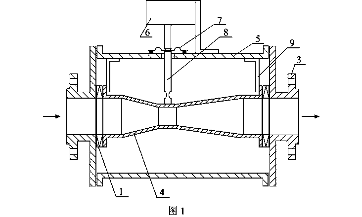
[0015] exist figure 1 In the embodiment, the dynamic Venturi tube 4 is built in a rigid pressure-resistant shell composed of the front end tube 3, the rear end tube 3 and the casing 5, and the weight of the dynamic Venturi tube 4 is determined by two pieces arranged at its two ends. Supported by two elastic supporting elements 9, in the present embodiment and the following embodiments, the elastic supporting elements 9 all adopt metal sheet slings 9, and the metal sheet slings 9 are made of very thin elastic metal sheets. is very small, so the rebound force generated by its deformation is also very small, so it can be considered that the thrust received by the moving Venturi tube 4 F It is only balanced by the rebound force of the force sensor 6 elastic elements. In this embodiment and the following embodiments, the elastic support element 9 can also be changed to a suspension wire, a cross-shaped leaf spring, a spoke-type circular spring and a flexible hinge. Most of the fl...
Embodiment 2
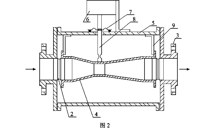
[0035] exist figure 2 In the implementation scheme, it can be seen that this example and figure 1 Embodiment 1 is substantially the same in structure, except that the flexible filter medium 1 is not filled in the two annular gaps between the moving Venturi tube 4 and the two end pipes 3, but two and end pipes 3 and 3 are used. A cylindrical filter membrane 2 with the same diameter as the movable venturi tube 4, the two ends of each filter membrane 2 are respectively connected to one end of the movable venturi tube 4 and the end pipe 3 near the end, and the filter membrane 2 can follow the moving The axial movement of the Venturi tube 4 makes the axial expansion and contraction of the same size to ensure that the fluid can only pass through the two filter membranes 2 to enter and exit the above two annular gaps. The cylindrical filter membrane 2 can be made of ordinary fiber fabric, or an inorganic microfiltration membrane or an organic microfiltration membrane using membrane...
Embodiment 3
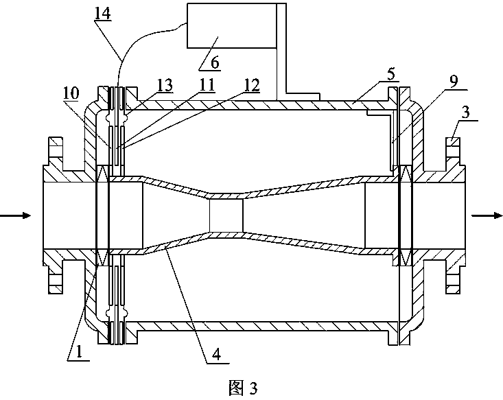
[0037] exist image 3 In the embodiment, the Venturi tube 4 is built in a rigid pressure-resistant shell composed of the front and rear end pipes 3 and the casing 5. Use two ring-shaped first capacitor outer pole plates 10 and the second capacitor outer pole plate 12, the inner edges of these two capacitor outer pole plates 10,12 are all sealed with the moving Venturi tube 4 front ends; Large and small circular capacitor inner plates 11, the outer edges of the capacitor inner plates 11 are fixedly connected to the rigid pressure-resistant housing, and the above three plates constitute a differential capacitance sensitive element. Two annular elastic diaphragms 13 are used, the outer edges of the two annular elastic diaphragms 13 are respectively sealed and connected with the rigid pressure-resistant housing, and the inner edges of the two annular elastic diaphragms 13 are not directly sealed and connected with the moving Venturi tube 4, Instead, it is connected to the outer e...
PUM
 Abstract
Description
Claims
Application Information
 - R&D
- Intellectual Property
- Life Sciences
- Materials
- Tech Scout
- Unparalleled Data Quality
- Higher Quality Content
- 60% Fewer Hallucinations
Browse by: Latest US Patents, China's latest patents, Technical Efficacy Thesaurus, Application Domain, Technology Topic, Popular Technical Reports.
© 2025 PatSnap. All rights reserved.Legal|Privacy policy|Modern Slavery Act Transparency Statement|Sitemap|About US| Contact US: help@patsnap.com


