
Model building system and equipment for architectural design

A technology for architectural design and architectural modeling, applied in shearing machine equipment, 3D modeling, metal processing equipment, etc., can solve the problems of not being in the same place, the structure is too simple, the operation of the staff is time-consuming and laborious, and the effect of ensuring the internal and external pressure is achieved.

Active Publication Date: 2022-06-24
河南省城乡规划设计研究总院股份有限公司
View PDF3 Cites 0 Cited by
  • Summary
  • Abstract
  • Description
  • Claims
  • Application Information

AI Technical Summary

Problems solved by technology

[0004] Aiming at the deficiencies of the prior art, the present invention provides a model building system and equipment for architectural design, which solves the problem that the existing architectural design model making devices are often too simple in structure, and usually the making station and the cutting station are not at the same place, resulting in In the production process, when cutting is required, it is necessary to leave the production station to the cutting station. The operation of the staff is time-consuming and laborious. The manufacturing device can only achieve a single function, and often requires production line workers to use multiple sets of equipment to operate. It takes a lot of time to assemble a group of architectural models

Method used


Image

  • Model building system and equipment for architectural design
  • Model building system and equipment for architectural design
  • Model building system and equipment for architectural design

Examples


Embodiment Construction

[0036] The technical solutions in the embodiments of the present invention will be clearly and completely described below with reference to the accompanying drawings in the embodiments of the present invention. Obviously, the described embodiments are only a part of the embodiments of the present invention, rather than all the embodiments. Based on the embodiments of the present invention, all other embodiments obtained by those of ordinary skill in the art without creative efforts shall fall within the protection scope of the present invention.

[0037] In this disclosure, terms such as "top", "bottom", "left", "right", "front", "rear", "vertical", "horizontal", "side", "bottom", etc. The orientation or positional relationship is based on the orientation or positional relationship shown in the drawings, and is only a relational word determined for the convenience of describing the structural relationship of each component or element of the present disclosure, and does not spec...


PUM


Abstract

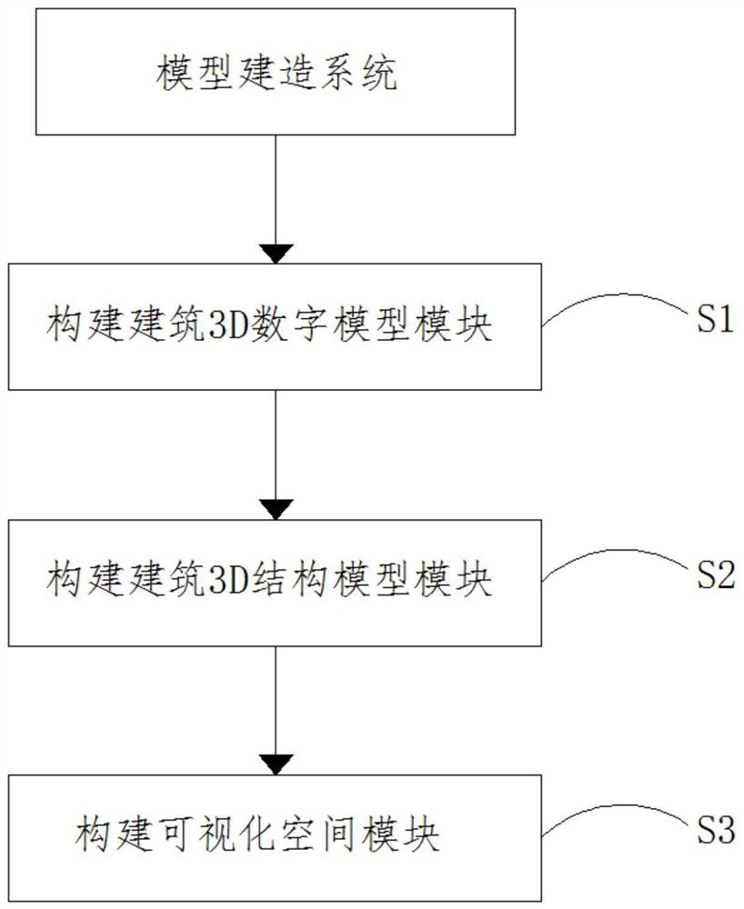
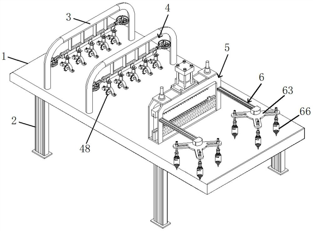
The invention relates to the technical field of light building material model design, and discloses a building design model building system, which comprises the following system templates: S1, building a building 3D digital model module; s2, building a building 3D structure model module; and S3, a visual space module is constructed, and model construction equipment for architectural design comprises an equipment body, a cutting mechanism, a clamping and flanging mechanism and a glue spraying mechanism, and the cutting mechanism, the clamping and flanging mechanism and the glue spraying mechanism are installed above the equipment body. According to the model building system and equipment for architectural design, a glue spraying head is driven by a rotating disc to rotate to any proper angle, the position of the glue spraying head connected to the lower portion of a sliding rod can be adjusted by controlling the sliding rod to slide in a sliding groove, the glue spraying head can conveniently reach any position to spray glue, and glue is sprayed by controlling the glue spraying head; and the manufacturing plate is moved to a glue spraying position, so that an automatic gluing function is realized.

Description

technical field [0001] The invention relates to the technical field of lightweight building material model design, in particular to a model building system and equipment for architectural design. Background technique [0002] In the modern design field, although computer software drawing is prevalent, for architectural design practitioners, the making of architectural models is an essential item. On the one hand, the designer's ideas cannot be more clearly displayed through the description of drawings, while the designer's ideas can be more intuitively displayed to the collaborators through the architectural model; on the other hand, the materials and Equipment should also be well prepared. The existing architectural design model making devices are often too simple in structure, and usually the production station and the cutting station are not in the same place. As a result, during the production process, when cutting is required, it is necessary to leave the production st...

Claims


Application Information

Patent Timeline
Patent Type & Authority Applications(China)
IPC IPC(8): G06F30/13G06F30/20G06T17/00B05B1/00B05B13/02B05B15/68B23D19/00B23D33/00B23Q11/00
CPCG06F30/13G06F30/20G06T17/00B23D19/00B23D33/00B23Q11/005B05B13/0221B05B15/68B05B1/00
Inventor 尹飞飞张志勇成利伟王琳高雪宁郭雪莉
Owner 河南省城乡规划设计研究总院股份有限公司
Learn More