
Efficient heat dissipation LED lamp bead based on heat dissipation area

A technology of LED lamp beads and heat dissipation area, which is applied in the direction of lighting and heating equipment, components of lighting devices, cleaning methods using tools, etc., which can solve high maintenance costs, reduce maintenance costs, large personnel and resource investment, etc. problem, achieve the effect of reducing energy consumption and use cost, improving stability and applicability

Active Publication Date: 2020-11-13
SHENZHEN DILUX LIGHTING TECH
View PDF9 Cites 4 Cited by
  • Summary
  • Abstract
  • Description
  • Claims
  • Application Information

AI Technical Summary

Problems solved by technology

In the future of the 21st century, lighting products using LED as the light source will inevitably replace white woven lamps and become another revolution in human lighting. After the LED lamp beads are used for a period of time, the lens surface of the lamp beads is easy to adhere to dust and be attracted by the light source. The remains of flying insects and other micro debris are usually cleaned by cleaning personnel by means of vibration and wiping, which requires a large investment in personnel and resources, and the maintenance cost is high. Therefore, a high-efficiency heat dissipation LED lamp bead based on heat dissipation area is proposed , the heat generated when the lamp beads emit light drives the cleaning device to automatically clean the lamp bead lens mirror surface, achieving the effect of automatic automatic cleaning and reducing maintenance costs

Method used


Image

  • Efficient heat dissipation LED lamp bead based on heat dissipation area
  • Efficient heat dissipation LED lamp bead based on heat dissipation area
  • Efficient heat dissipation LED lamp bead based on heat dissipation area

Examples


Embodiment

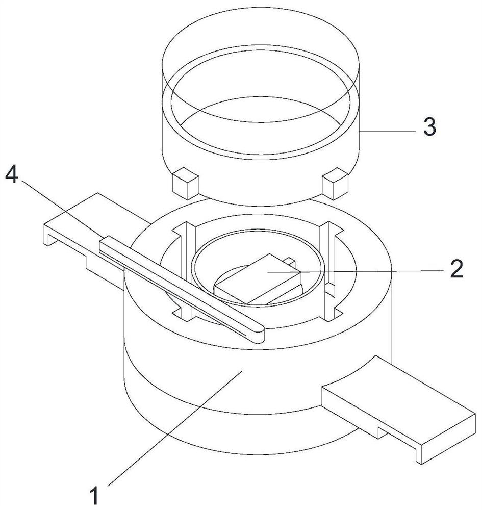
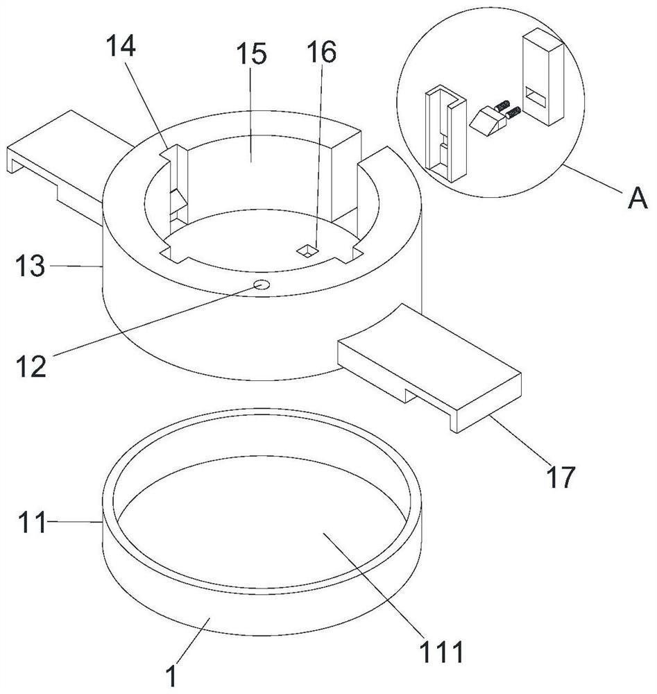
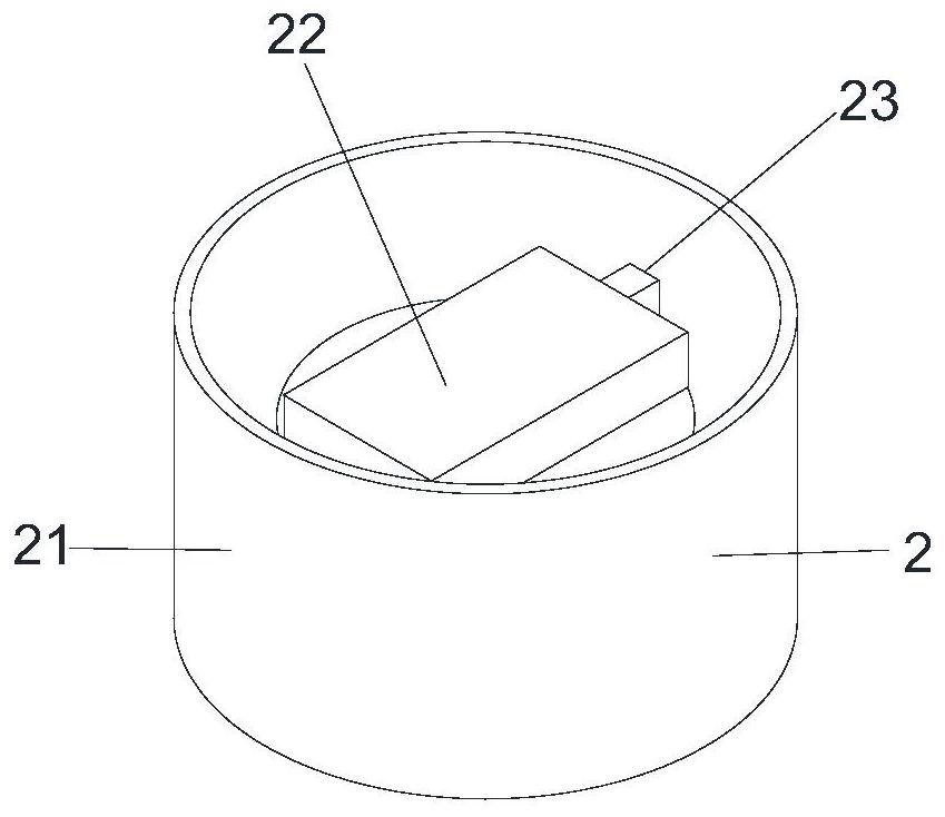
[0025] Embodiment: a kind of high-efficiency heat dissipation LED lamp bead based on heat dissipation area, such as Figure 1-Figure 6 Shown, comprise support 1, support 1 comprises frame body 13, two fixed mounts 17 and four slide grooves 14, the lower surface of frame body 11 is provided with chassis 11, and the upper surface of chassis 11 is fixed with the lower surface of frame body 13 Connection, the middle part of the upper surface of the chassis 11 is provided with a circular groove one 111, and a sweeping device 4 is arranged in the circular groove one 111, and the sweeping device 4 includes a sweeping rod 45, a rotating rod 43 and a liquid storage cylinder 41, and the liquid storage cylinder The front end of 41 is provided with telescopic rod 48, the lower surface of heat conducting rod one 23 is provided with heat conducting rod two 47, the lower surface of heat conducting rod one 23 is fixedly connected with the left end of the upper surface of heat conducting rod tw...


PUM


Abstract

The invention relates to the field of LED lamp bead equipment. The invention discloses an efficient heat dissipation LED lamp bead based on a heat dissipation area. The efficient heat dissipation LEDlamp bead comprises a support, the support comprises a support body, two fixing frames and four sliding grooves, a chassis is arranged on the lower surface of the frame body, the upper surface of thechassis is fixedly connected with the lower surface of the frame body, a circular groove I is formed in the middle of the upper surface of the chassis, a sweeping device is arranged in the circular groove I, a circular groove II is formed in the middle of the upper surface of the frame body, the support can be separated from a lampshade, due to the design, the stability of the LED lamp component is improved, the lampshade is not easy to displace in the subsequent sweeping process, so that the normal use of the LED lamp is not influenced, the rotating rod rotates to drive the sweeping rod to rotate to achieve an automatic sweeping effect on the lens, the temperature around the lamp wick is reduced, heat generated by light emitting of the LED lamp is effectively absorbed and utilized, the rotating piece is reset through the second spring after the rotating piece loses the pushing force of the telescopic rod, sweeping operation can be conducted again when the LED lamp is started again, and the automatic reset effect is achieved.

Description

technical field [0001] The invention relates to the field of LED lamp bead equipment, in particular to a high-efficiency heat dissipation LED lamp bead based on the heat dissipation area. Background technique [0002] The full name of LED is semiconductor light-emitting diode. It is made of semiconductor materials and is a light-emitting device that directly converts electrical energy into light energy and electrical signals into optical signals. It is characterized by low power consumption, high brightness, bright colors, anti-vibration, and long life. Long (80,000-100,000 hours of normal light emission), cold light source and other advantages, it is a real "green lighting". In the future of the 21st century, lighting products using LED as the light source will inevitably replace white woven lamps and become another revolution in human lighting. After the LED lamp beads are used for a period of time, the lens mirror surface of the lamp beads is easy to adhere to dust and be...

Claims


Application Information

Patent Timeline
IPC IPC(8): F21K9/20F21V29/50F21V33/00F21V17/16B08B11/00B08B1/04F21Y115/10
CPCF21K9/20F21V29/50F21V33/00F21V17/162B08B11/00F21Y2115/10B08B1/32
Inventor 陈业凤陶静
Owner SHENZHEN DILUX LIGHTING TECH
Learn More