
Coal underground explosion-proof LED illuminating lamp

A technology of LED lighting and LED light source, applied in lighting applications, lighting devices, lighting devices, etc., can solve problems such as poor explosion-proof effect, and achieve the effect of reducing possibility, improving safety performance, and good explosion-proof effect.

Inactive Publication Date: 2020-11-13
方玉玲
View PDF5 Cites 0 Cited by
  • Summary
  • Abstract
  • Description
  • Claims
  • Application Information

AI Technical Summary

Problems solved by technology

[0005] The object of the present invention is to provide a self-adjustable explosion-proof LED lighting lamp for underground coal mines with good explosion-proof effect for the above-mentioned problems of blocking light and poor explosion-proof effect

Method used


Image

  • Coal underground explosion-proof LED illuminating lamp
  • Coal underground explosion-proof LED illuminating lamp

Examples


Embodiment 1

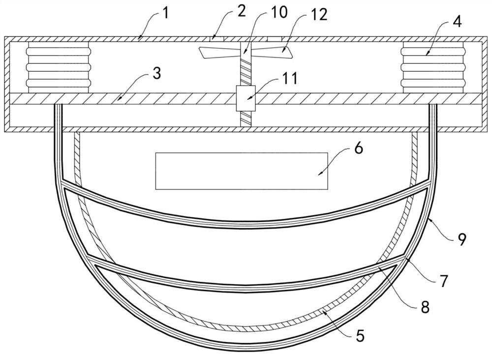
[0019] like figure 1 As shown, an explosion-proof LED lighting lamp for coal mines includes a mounting seat 1 and an LED light source 6. A ventilation hole 2 is opened on the side wall of the mounting seat 1, and a horizontally arranged lifting plate 3 is slidably connected to the inner side wall of the mounting seat 1. , the upper surface of the lifting plate 3 is fixedly connected with the inner top surface of the mounting seat 1 through the elastic air bag 4, the bottom of the mounting seat 1 is mounted with a transparent cover 5 arranged in a hemispherical shape, the LED light source 6 is installed in the transparent cover 5, and the transparent cover 5. A protective net 7 is provided outside, and the protective net 7 is woven from a plurality of ribs 8. The upper end of the protective net 7 penetrates the bottom surface of the mounting seat 1 and is fixedly connected with the lifting plate 3. The plurality of ribs 8 are sleeved with The expansion tube 9, a plurality of ex...

Embodiment 2

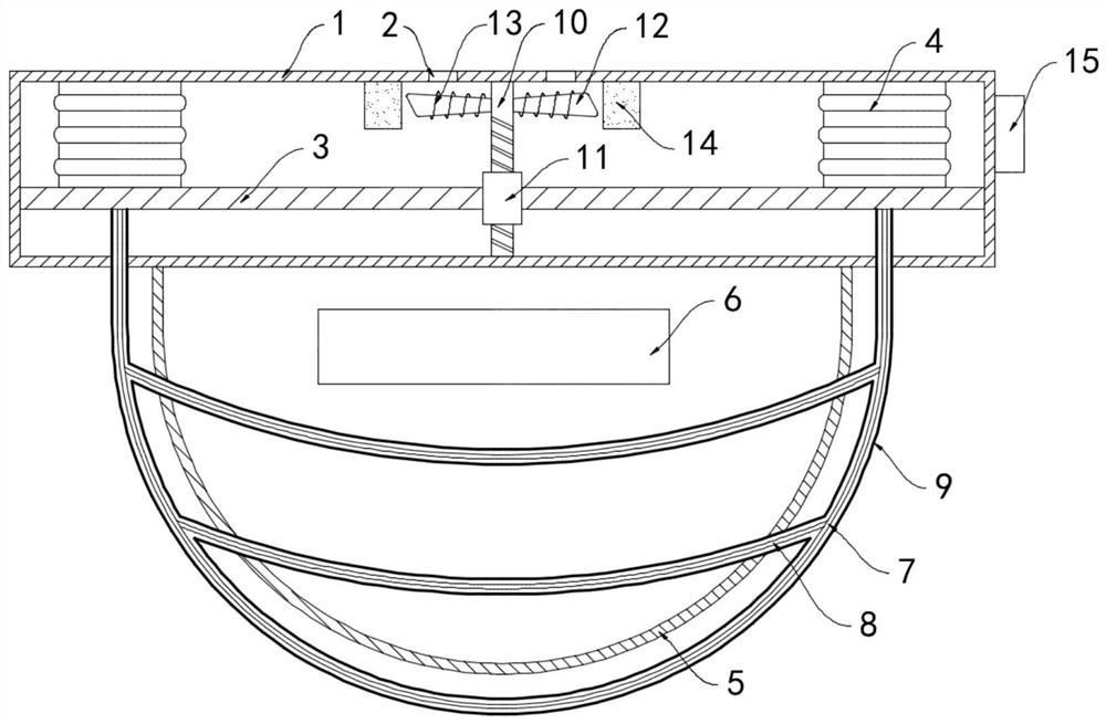
[0024] like figure 2 As shown, the difference between this embodiment and Embodiment 1 is that a helical coil 13 is wound around the fan blade of the fan 12, a permanent magnet ring 14 is fixedly connected to the inner top surface of the mounting seat 1, and the permanent magnet ring 14 is sleeved Outside the fan 12, the winding direction of the helical coil 13 is perpendicular to the direction of the magnetic field lines inside the permanent magnet ring 14. During the rotation of the helical coil 13, the magnetic field lines in the permanent magnet ring 14 can be continuously cut to generate an induced current. A buzzer piece 15 is installed on the side wall of the horn, and the positive and negative poles of the buzzer piece 15 are coupled and connected to both ends of the spiral coil 13 respectively.

[0025] In this embodiment, when the protective net 7 is squeezed by the collision, the fan 12 drives the spiral coil 13 to rotate. According to the principle of electromagne...


PUM


Abstract

The invention belongs to the field of LED lamps and relates to a coal underground explosion-proof LED illuminating lamp. The lamp comprises a mounting base and an LED light source, a lifting plate which is horizontally arranged is connected to the inner side wall of the mounting base in a sliding manner, the upper surface of the lifting plate is fixedly connected with the inner top surface of themounting base through an elastic air bag, a semispherical transparent cover is mounted at the bottom of the mounting base, the LED light source is installed in the transparent cover, a protective netis arranged outside the transparent cover, the protective net is formed by weaving a plurality of ribs, the upper end of the protective net penetrates through the bottom face of the installation baseand is fixedly connected with the lifting plate, the ribs are sleeved with expansion pipes, and the expansion pipes are communicated with the elastic air bag. By arranging the expansion pipe, in the normal state, the collision pipe contracts and is tightly attached to the ribs, light emitted by the LED light source is shielded a little, when the protective net is collided and extruded, the expansion pipe is inflated and expanded, the protective area of the transparent cover is increased, and meanwhile a good buffering effect is provided.

Description

technical field [0001] The invention belongs to the field of LED lamps, in particular to an explosion-proof LED lighting lamp for underground coal mines. Background technique [0002] Due to the narrow space in the coal shaft, LED lighting needs to be installed on both sides of the shaft to ensure the safety of construction. However, the staff and the excavation machinery in the shaft are easy to collide with the lighting and cause safety problems, so the LED lighting needs to have good explosion-proof performance. . [0003] Most of the traditional explosion-proof LED lights are equipped with a metal protective net outside the lampshade. When the lighting lamp is working, the surface temperature of the metal protective net is high, and it is very easy to cause burns if the staff accidentally touches it. If all the protective nets are sparsely distributed, it is difficult to achieve a good explosion-proof effect. [0004] To this end, we propose a coal mine explosion-proof...

Claims


Application Information

Patent Timeline
Patent Type & Authority Applications(China)
IPC IPC(8): F21S8/00F21V15/04F21V29/67F21V33/00F21W131/402F21Y115/10
CPCF21S8/00F21V15/04F21V33/0076F21W2131/402F21V29/67F21Y2115/10
Inventor 方玉玲于小辉
Owner 方玉玲
Learn More