Multifunctional lighting system

A lighting system and multi-functional technology, applied in the direction of lighting devices, fixed lighting devices, lighting auxiliary devices, etc., can solve the problems of unable to meet actual needs, unable to diverge from multiple points, unable to meet user needs, etc.

Pending Publication Date: 2020-11-13
ROMNEY OPTO ELECTRONICS SYST TECH GUANGDONG CO LTD
View PDF2 Cites 0 Cited by
  • Summary
  • Abstract
  • Description
  • Claims
  • Application Information

AI Technical Summary

Problems solved by technology

[0003] Chinese utility model patent CN208546766U (disclosure date: February 26, 2019) discloses modular combined lamps that can be combined flexibly, but it has high requirements for the structure of the lighting module, and the lighting module needs to be constructed into a special shape before it can be combined end to end , cannot flexibly combine the existing lighting products on the market, the combined lamps can only extend on one plane, and can only diverge at a single point through the design of the lamp holder, and cannot diverge at multiple points, and the lighting module needs to be disassembled The position can only be changed, and the function is still relatively single, which cannot meet the actual needs of some applications.
Chinese utility model patent CN209278922U (disclosure date: August 20, 2019) discloses the use of magnetic suction low pressure to fix lamps, but the lighting device can only change its position

Method used


Image

  • Multifunctional lighting system
  • Multifunctional lighting system
  • Multifunctional lighting system

Examples


Embodiment 1

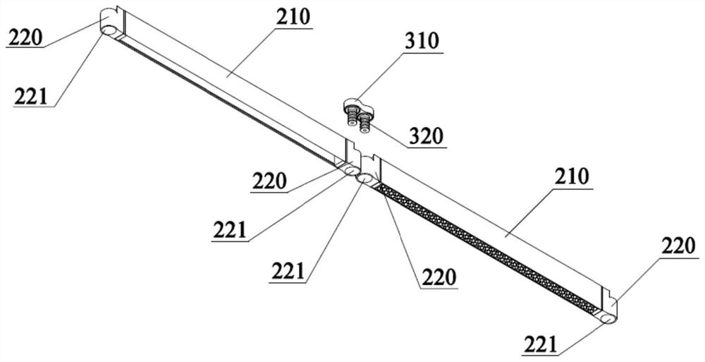
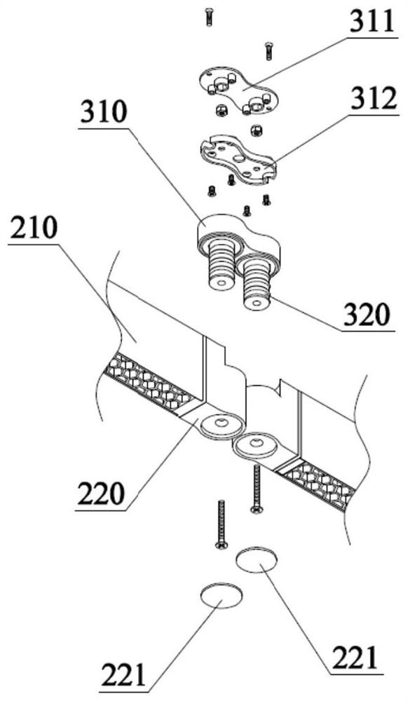
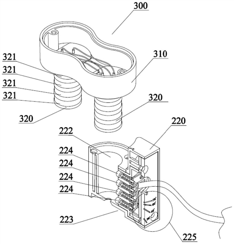
[0055] figure 1 It is a schematic structural diagram of a multifunctional lighting system according to an embodiment of the present invention. figure 2 It is an exploded view of the installation of the connection module and the light source module according to an embodiment of the present invention. image 3 It is a schematic structural diagram of a connection module installed with a second connection port according to an embodiment of the present invention, wherein the second connection port is cut along its central axis to show its internal structure. Figure 4 It is a schematic structural diagram from another perspective of the installation of the connection module and the second connection port according to an embodiment of the present invention. Figure 5 for figure 2 Schematic diagram of the rotation of the light source module relative to the connection module.

[0056] like figure 1 , figure 2 As shown, a multifunctional lighting system includes a power module 1...

Embodiment 2

[0063] Image 6 It is a schematic diagram of the installation of the swing fixing member in the light source module according to an embodiment of the present invention. Figure 7 for Image 6 A schematic diagram of the main body of the light source module rotating relative to the second connection port. Figure 8 for figure 1 Schematic diagram of the rotation state of the multifunctional lighting system, wherein the main body of the light source module is rotated at a certain angle relative to the second connection port, and the second connection port not connected with the connection module is installed with a tail end module. Figure 9 for Figure 4 The scale indicates an enlarged view of the element.

[0064] This embodiment is the second embodiment of the multi-functional lighting system of the present invention. Different from the first embodiment, the light source module 200 further includes a swing fixing member 240 and a connecting rod 241 . A part of the swing fi...

Embodiment 3

[0068] Figure 10 It is a schematic diagram of the lamps in the track light module moving along the track light module according to an embodiment of the present invention, Figure 11 It is a schematic diagram of installing two lamps in a track lamp module according to an embodiment of the present invention, Figure 12 It is a schematic structural diagram of a track light module according to an embodiment of the present invention.

[0069] This embodiment is the third embodiment of the multi-functional lighting system of the present invention. Different from the first embodiment, the light source module 200 includes a track light module, and the track light module includes at least one lamp 230 that can move along the track light module, such as Figure 10 , Figure 11 shown. It can be understood that both the light source module 200 and the light fixture 230 may be one or more of a grill light, a honeycomb light, a flat light, a spot light, a chandelier, and a ceiling light...


PUM


Abstract

The invention relates to the technical field of lighting equipment, and in particular, relates to a multifunctional lighting system. The multifunctional lighting system comprises a power supply module, at least two light source modules and at least one connecting module, the connection module comprises a connection module main body and at least two first connection ports connected to the connection module main body. Each light source module is provided with a light source template main body and at least one second connecting port connected to the light source template main body; the first connecting ports are electrically connected with the second connecting ports, the number of the first connecting ports of one connecting module corresponds to the number of the light source modules connected with the connecting module, and any connecting module can be electrically connected with the power supply module. The multifunctional lighting system is novel in structure, more flexible and flexible, capable of combining desired appearance structures at will, capable of meeting various requirements of different practical application places, diversified in function and capable of meeting functional place lighting design requirements which cannot be met by other conventional products.

Description

technical field [0001] The present invention relates to the technical field of lighting equipment, and more particularly, to a multifunctional lighting system. Background technique [0002] At present, the functionality of many lighting products is relatively single, and often cannot better meet the various needs of practical application sites. For example, some products on the market have the same basic purpose, and substitutes can be found at will, and they are not competitive. [0003] Although the modular combined lamps disclosed in Chinese utility model patent CN208546766U (publication date: February 26, 2019) can be combined flexibly, they have high requirements on the structure of the lighting modules, and the lighting modules need to be constructed into special shapes to be able to be combined end to end , can not flexibly combine the existing lighting products on the market, the combined lamps can only extend on one plane, and can only diverge from a single point t...

Claims


Application Information

Patent Timeline
IPC IPC(8): F21S8/00F21V17/16F21V17/12F21V17/10F21V21/34F21V21/22F21V14/02
CPCF21S8/00F21V14/02F21V17/10F21V17/12F21V17/164F21V21/22F21V21/34
Inventor 彭银水
Owner ROMNEY OPTO ELECTRONICS SYST TECH GUANGDONG CO LTD
Why Eureka
Try Eureka