
Vacuum reaction system for grain boundary diffusion technology

A technology of reaction system and grain boundary diffusion, applied in lighting and heating equipment, furnace components, furnace types, etc., can solve the problems of slow cooling speed of sintering equipment and inability to achieve rapid cooling

Pending Publication Date: 2020-11-13
北京北方华创磁电科技有限公司
View PDF0 Cites 2 Cited by
  • Summary
  • Abstract
  • Description
  • Claims
  • Application Information

AI Technical Summary

Problems solved by technology

[0004] The above related technical solutions have the following defects: after the magnetic material is heated at high temperature in the sintering equipment, it is necessary to wait until the temperature inside the sintering equipment drops to normal temperature before the magnetic material can be taken out from the sintering equipment. The inventor believes that the cooling speed of the sintering equipment Slow, unable to achieve rapid cooling

Method used


Image

  • Vacuum reaction system for grain boundary diffusion technology
  • Vacuum reaction system for grain boundary diffusion technology
  • Vacuum reaction system for grain boundary diffusion technology

Examples


Embodiment Construction

[0035] The application will be described in further detail below in conjunction with the accompanying drawings.

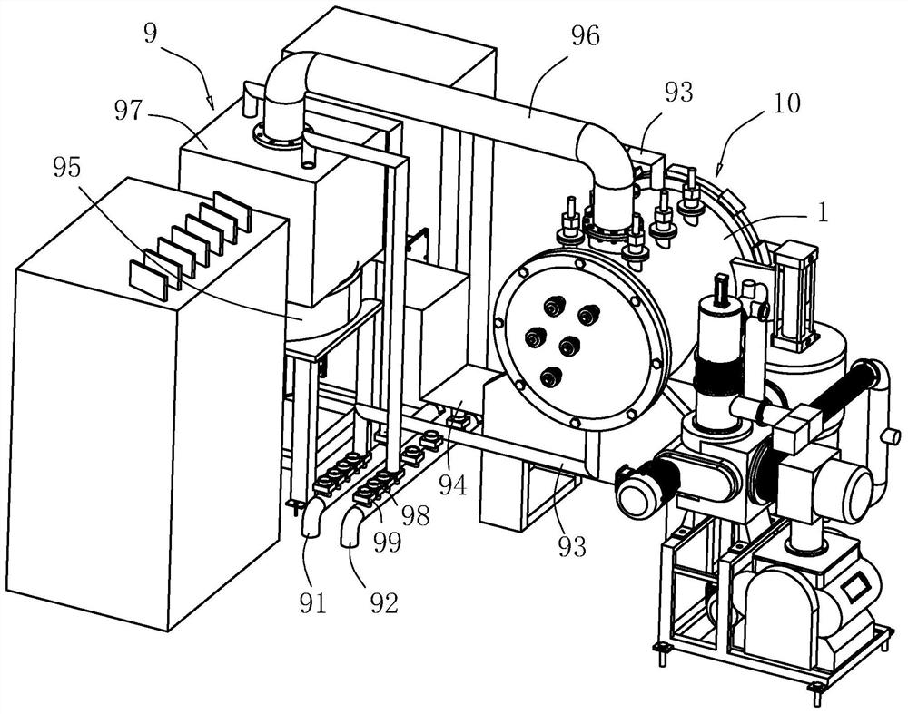
[0036] refer tofigure 1 , the present application provides a vacuum reaction system for grain boundary diffusion process, including a vacuum furnace 10 capable of heating internal workpieces and a rapid cooling device 9 arranged outside the vacuum furnace 10 and capable of cooling the vacuum furnace 10 .

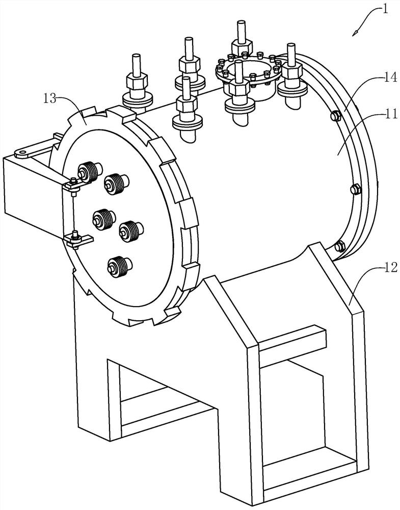
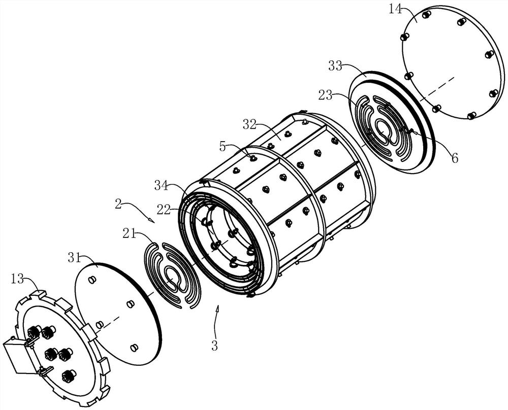
[0037] refer to figure 2 with image 3 , the vacuum furnace 10 includes a furnace body 1, a heater 2 arranged in the furnace body 1, and a reflective screen 3 between the furnace body 1 and the heater 2; the furnace body 1 is mainly used to place workpieces to be processed; the heater 2 is mainly used to heat the workpiece at high temperature; the reflective screen 3 is mainly used to keep the furnace body 1 warm and insulated.

[0038] refer to figure 2 , the furnace body 1 includes a furnace shell 11 with a hollow interior and open ends at both ends. The f...


PUM


Abstract

The invention relates to the technical field of grain boundary diffusion technologies, in particular to a vacuum reaction system for a grain boundary diffusion technology. The vacuum reaction system comprises a vacuum furnace capable of heating a workpiece, a furnace body of the vacuum furnace comprises a hollow furnace shell, and the outer side of the vacuum furnace is provided with a rapid cooling device; and the rapid cooling device comprises a water supply pipe and a water return pipe of which one ends are sealed, and the water supply pipe and the water return pipe communicate with the interior of an cavity inside the furnace shell through communication pipes. The vacuum reaction system has the effects of increasing the cooling speed of sintering equipment and achieving rapid cooling of the sintering equipment.

Description

technical field [0001] The present application relates to the technical field of grain boundary diffusion technology, in particular to a vacuum reaction system for grain boundary diffusion technology. Background technique [0002] At present, in the industrial production of the magnetic material industry, it is generally used to increase the coercive force by doping heavy rare earth materials together in the smelting process. In order to obtain higher performance of the magnet more effectively, the process of infiltration of heavy rare earth grain boundaries is adopted to effectively reduce the usage of heavy rare earth elements, so that heavy rare earth elements only exist in the grain boundaries, so that it is easier to obtain high-performance magnets. [0003] The existing heavy rare earth infiltration process mainly includes: forming a layer of thin film containing heavy rare earth elements on the surface of the workpiece by evaporation or coating, and then performing hi...

Claims


Application Information

Patent Timeline
IPC IPC(8): F27B5/05F27B5/14F27B5/16F27D1/12F27D1/18H01F41/02
CPCF27B5/04F27B5/14F27B5/16F27B2005/064F27B2005/143F27B2005/166F27D1/12F27D1/18H01F41/0293
Inventor 张永军
Owner 北京北方华创磁电科技有限公司
Learn More