Optical system, camera module and electronic equipment

A technology of optical system and camera module, applied in optics, optical components, instruments, etc., can solve problems such as driving risks

Pending Publication Date: 2020-11-13
TIANJIN OFILM OPTO ELECTRONICS CO LTD
View PDF0 Cites 0 Cited by
  • Summary
  • Abstract
  • Description
  • Claims
  • Application Information

AI Technical Summary

Problems solved by technology

[0003] However, the existing front-view camera lens is difficult to meet the clear imaging of a large-angle range, and cannot accurately judge obstacles in a large-angle range in real time to avoid them, which leads to the existence of driving risks.

Method used


Image

  • Optical system, camera module and electronic equipment
  • Optical system, camera module and electronic equipment
  • Optical system, camera module and electronic equipment

Examples


no. 1 example

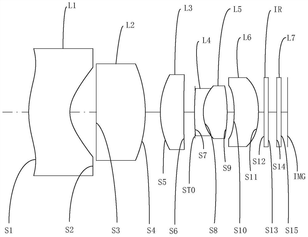
[0053] Please refer to Figure 1a and Figure 1b , the optical system of this embodiment includes in sequence from the object side to the image side along the optical axis direction:

[0054] The first lens L1 has a negative refracting force. The object side S1 of the first lens L1 is convex at the near optical axis and concave at the circumference; the image side S2 of the first lens L1 is concave at the near optical axis and concave at the circumference. place is flat;

[0055] The second lens L2 has a positive refractive power, the object side S3 of the second lens L2 is a plane, and the image side S4 is a convex surface;

[0056] The third lens L3 has a positive refractive power, the object side S5 of the third lens L3 is a convex surface, and the image side S6 is a concave surface;

[0057] The fourth lens L4 has negative refractive power, the object side S7 of the fourth lens L4 is convex, and the image side S8 is concave;

[0058] The fifth lens L5 has a positive ref...

no. 2 example

[0074] Please refer to Figure 2a and Figure 2b , the optical system of this embodiment includes in sequence from the object side to the image side along the optical axis direction:

[0075] The first lens L1 has a negative refracting force. The object side S1 of the first lens L1 is convex at the near optical axis and concave at the circumference; the image side S2 of the first lens L1 is concave at the near optical axis and concave at the circumference. place is flat;

[0076] The second lens L2 has a positive refractive power, the object side S3 of the second lens L2 is a plane, and the image side S4 is a convex surface;

[0077] The third lens L3 has a positive refractive power, the object side S5 of the third lens L3 is a convex surface, and the image side S6 is a concave surface;

[0078] The fourth lens L4 has negative refractive power, the object side S7 of the fourth lens L4 is convex, and the image side S8 is concave;

[0079] The fifth lens L5 has a positive re...

no. 3 example

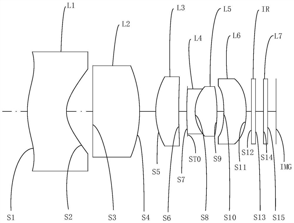
[0090] Please refer to Figure 3a and Figure 3b , the optical system of this embodiment includes in sequence from the object side to the image side along the optical axis direction:

[0091] The first lens L1 has a negative refracting force. The object side S1 of the first lens L1 is convex at the near optical axis and concave at the circumference; the image side S2 of the first lens L1 is concave at the near optical axis and concave at the circumference. place is flat;

[0092] The second lens L2 has a positive refractive power, the object side S3 of the second lens L2 is a plane, and the image side S4 is a convex surface;

[0093] The third lens L3 has a positive refractive power, the object side S5 of the third lens L3 is a convex surface, and the image side S6 is a plane;

[0094] The fourth lens L4 has negative refractive power, the object side S7 of the fourth lens L4 is convex, and the image side S8 is concave;

[0095] The fifth lens L5 has a positive refractive p...


PUM


Abstract

An optical system, a camera module and electronic equipment are provided. The optical system includes, in order from an object side to an image side: a first lens element with negative meandering force, an object-side surface of the first lens element being convex in a paraxial region thereof, and an image-side surface of the first lens element being concave in a paraxial region thereof; the second lens has positive bending force, and the object side surface of the second lens is a plane; a third lens having a positive meandering force; a fourth lens element with negative refractive power; a fifth lens element with positive refractive power; and a sixth lens having a positive meandering force. By reasonably configuring the surface types and the bending force of the first to sixth lenses, the optical system has a large field angle, the optical system can meet the design requirement of clear imaging in a large angle range, and the safety of a driving environment in the large angle rangecan be accurately judged in real time. And meanwhile, the object side surface of the second lens is a plane, so that the assembling eccentricity sensitivity of the second lens is reduced, the assembling yield is further improved, and the production cost is reduced.

Description

technical field [0001] The invention belongs to the field of optical imaging, and in particular relates to an optical system, a camera module and electronic equipment with the optical system. Background technique [0002] With the development of the vehicle industry, the technical requirements for vehicle cameras such as front view, automatic cruise control, driving recorder, and reversing image are getting higher and higher. The front-view camera is a vehicle-mounted camera installed in front of the car. It can be used as a camera in an advanced driver assistance system to analyze video content and provide lane departure warning (Lane Departure Warning, LDW), automatic lane keeping assistance (Lane Keep Assistance, LKA) and Services such as high beam / low beam control and traffic sign recognition (TrafficSign Recognition, TSR). When it is turned on when parking, you can intuitively see the obstacles in front of the car, making parking more convenient. When the car passes t...

Claims


Application Information

Patent Timeline
Patent Type & Authority Applications(China)
IPC IPC(8): G02B13/00G02B13/06G02B13/18
CPCG02B13/0045G02B13/006G02B13/06G02B13/18
Inventor 蔡雄宇兰宾利周芮
Owner TIANJIN OFILM OPTO ELECTRONICS CO LTD
Why Eureka
Try Eureka