
Parameter configuration method

A parameter configuration method and a parameter configuration technology, applied in the field of sensors, can solve problems such as high cost of parameter configuration, increased power consumption, complex circuits, etc., and achieve the effects of avoiding downgraded use or scrapping, saving resources, and reducing costs

Pending Publication Date: 2020-11-13
上海沪振物联技术有限公司
View PDF1 Cites 0 Cited by
  • Summary
  • Abstract
  • Description
  • Claims
  • Application Information

AI Technical Summary

Problems solved by technology

If you only modify simple parameters, due to the layout of the current conversion chip of the control circuit, the overall circuit is more complicated, power consumption increases, and the overall volume of the sensor increases; in addition, the dedicated HART handheld is more expensive, resulting in parameter configuration costs. high

Method used


Image

  • Parameter configuration method
  • Parameter configuration method

Examples


Embodiment 1

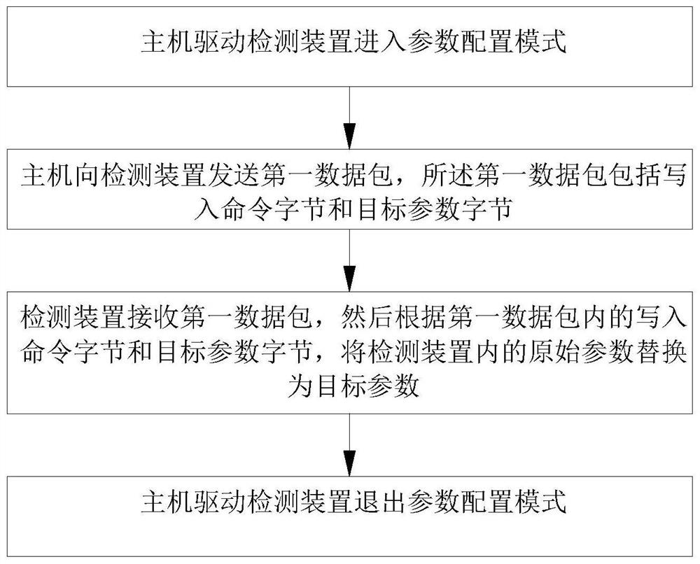
[0049] This embodiment provides a parameter configuration method, such as figure 1 As shown, the parameter configuration method is implemented based on a parameter configuration system; the parameter configuration system includes a detection device and a host, and the detection device is electrically connected to the host. Specifically, the parameter configuration method is used to configure the original parameters of the detection device; the host can be, but not limited to, any one of a mobile phone, a tablet computer, a notebook computer, and a desktop computer, and is used to realize reading the original parameters in the detection device , and configure the parameters of the detection device. The parameter configuration method includes the following steps:

[0050] The host drives the detection device to enter the parameter configuration mode;

[0051] The host sends a first data packet to the detection device, and the first data packet includes a write command byte and...

Embodiment 2

[0058] A parameter configuration method such as figure 1 As shown, the parameter configuration method is implemented based on a parameter configuration system; the parameter configuration system includes a detection device and a host, and the detection device is electrically connected to the host; the parameter configuration method is used to configure the original parameters of the detection device;

[0059] Specifically, in this embodiment, the detection device includes a sensor, a processor, and a loop power supply circuit that are electrically connected in sequence, and the loop power supply circuit is electrically connected to the host; the detection device also includes a power supply circuit, and the power supply The controlled end of the circuit is electrically connected to the loop power supply circuit, and the power output end of the power supply circuit is electrically connected to the sensor and the processor; the parameter configuration method is used to configure ...


PUM


Abstract

The invention relates to the technical field of sensors, and aims to provide a parameter configuration method. The parameter configuration method is realized based on a parameter configuration system.The parameter configuration system comprises a detection device and a host. The detection device is electrically connected with the host. The parameter configuration method comprises the following steps: the host drives the detection device to enter a parameter configuration mode; the host sends a first data packet to the detection device, wherein the first data packet comprises a write command byte and a target parameter byte; the detection device receives the first data packet, and replaces the original parameters in the detection device with the target parameters according to the write-incommand bytes and the target parameter bytes in the first data packet; and the host drives the detection device to exit the parameter configuration mode. The parameter configuration cost of the detection device is low.

Description

technical field [0001] The invention relates to the technical field of sensors, in particular to a parameter configuration method. Background technique [0002] The two-wire sensor is generally powered by 24V (15-30V), and the loop outputs a 4-20mA signal. 4mA represents the minimum value of the sensor’s measurement range, 20mA represents the maximum value of the range, and the change of current between 4-20mA represents As the measured value changes within the range, if the range value is known, the measured value can be calculated through the sensor output current. [0003] At present, most of the two-wire sensors have a unique fixed range, and many sensors are sealed by welding or glue filling. Once the production is completed, it is difficult to adjust the parameters. After long-term use, the sensor is prone to parameter drift and low precision. If the parameters are changed forcibly at this time, it is necessary to physically damage the sensor shell or internal structu...

Claims


Application Information

Patent Timeline
Patent Type & Authority Applications(China)
IPC IPC(8): G06F9/445G01D18/00
CPCG06F9/44505G01D18/00
Inventor 王亮张伏贺园
Owner 上海沪振物联技术有限公司
Learn More