Optimization method of line laser vision inertial system

A technology of inertial system and optimization method, which is applied to the details of 3D image data, image data processing, measurement devices, etc., can solve the problems of size drift displacement, measurement accuracy and low efficiency, and improve accuracy and robustness Effect

Pending Publication Date: 2020-11-13
BOYA GONGDAO BEIJING ROBOT TECH CO LTD
View PDF0 Cites 7 Cited by
  • Summary
  • Abstract
  • Description
  • Claims
  • Application Information

AI Technical Summary

Problems solved by technology

[0005] Aiming at the problems in the related technologies, the present invention proposes an optimization method of the line laser visual inertial

Method used


Image

  • Optimization method of line laser vision inertial system
  • Optimization method of line laser vision inertial system
  • Optimization method of line laser vision inertial system

Examples


Example Embodiment

[0021] The technical solutions in the embodiments of the present invention will be clearly and completely described below with reference to the accompanying drawings in the embodiments of the present invention. Obviously, the described embodiments are only a part of the embodiments of the present invention, rather than all the embodiments. Based on the embodiments in the present invention, all other embodiments obtained by those of ordinary skill in the art fall within the protection scope of the present invention.

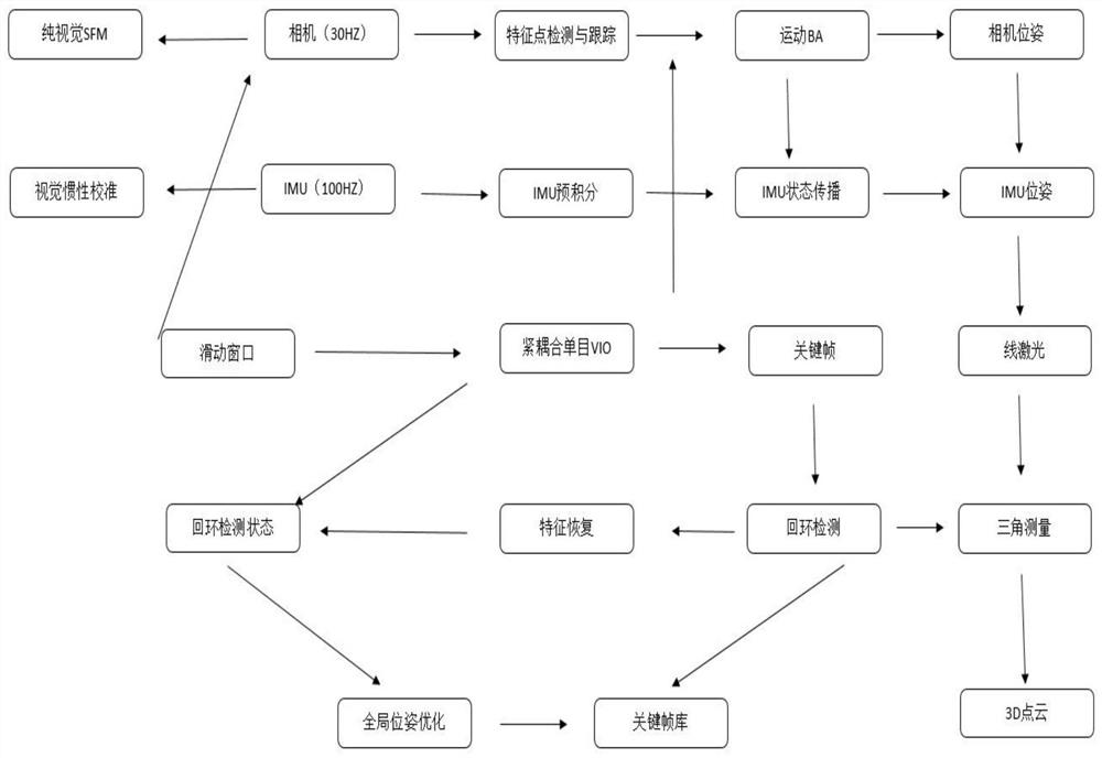
[0022] A method for optimizing a line laser visual inertial system according to an embodiment of the present invention includes the following steps:

[0023] Step S1, pre-process the measurement data, read the image data of the camera sensor through visual SLAM, perform feature point tracking in the visual front-end, pre-integrate the gyroscope bias of the inertial navigation sensor IMU between two consecutive frames, and integrate The laser triangulation curve is...


PUM


Abstract

The invention discloses an optimization method for a line laser vision inertial system, and the method comprises the steps: S1, carrying out the preprocessing of measurement data; S2, initializing anestimator; S3, obtaining an initial value by adopting a loose coupling sensor fusion method; S4, repositioning the sliding window; S5, optimizing the global pose graph; and S6, according to the globalpose and the laser triangulation depth of each pose, fusing to form a final 3D model. According to the optimization method, the final 3D model can be optimized, and the accuracy and robustness of theline laser vision inertial system are improved.

Description

technical field [0001] The invention relates to the technical field of underwater intelligent scanning, in particular to an optimization method of a line laser visual inertial system. Background technique [0002] Simultaneous Localization and Mapping (SLAM technology for short) is an important direction of mobile robot positioning and navigation technology. .Because the camera is cheaper and smaller than the laser sensor, and the acquired image contains richer information, vision-based SLAM, referred to as visual SLAMD technology, has become a research hotspot: compared with the binocular camera and RGB-D depth camera, monocular camera has the advantages of low power consumption, small size, light weight, etc., especially on the platform of small mobile robots (such as micro drones). Therefore, monocular SLAM technology can be applied to Different mobile robot platforms have important research value. [0003] However, only relying on the monocular camera information for t...

Claims


Application Information

Patent Timeline
IPC IPC(8): G06T17/05G01C21/00G01C21/16
CPCG01C21/005G01C21/165G06T17/05G06T2200/04
Inventor 熊明磊陈龙冬李鑫海
Owner BOYA GONGDAO BEIJING ROBOT TECH CO LTD
Why Eureka
Try Eureka