A sensorless brushless DC motor rotor position detection system and method in a static state

A technology for rotor position detection and brushing of DC motors, which is used in AC motor control, control systems, and generator control. The effect of small, short positioning time

Active Publication Date: 2022-02-15
苏州崧崧智能控制技术有限公司
View PDF5 Cites 0 Cited by
  • Summary
  • Abstract
  • Description
  • Claims
  • Application Information

AI Technical Summary

Problems solved by technology

Zhao Baige used the principle of magnetic circuit saturation effect in the paper "Research on Sensorless Control Method of Brushless DC Motor Based on Line Back EMF Estimation [D]. (Harbin Institute of Technology, 2017)" and used six detection pulse voltages with different conduction directions For initial position detection, the positioning time is shortened by reducing the number of detection pulses injected, but the detection accuracy of this method only reaches 60°, and the positioning time is shortened by sacrificing the detection accuracy
Wang Huabin combined the saliency effect of the saliency motor and the principle of magnetic circuit saturation effect in the paper "Permanent Magnet Brushless DC Motor Position Sensorless Control Based on Indirect Inductance Method. Chongqing University, 2009", and detected the pulse voltage by injecting 8 times , using the terminal voltage and current information to judge the initial position of the rotor. On the basis of achieving 30° high-precision positioning, this scheme reduces the number of detection pulses and shortens the positioning time. However, compared with other schemes, there is still an improvement in the positioning time. space

Method used


Image

  • A sensorless brushless DC motor rotor position detection system and method in a static state
  • A sensorless brushless DC motor rotor position detection system and method in a static state
  • A sensorless brushless DC motor rotor position detection system and method in a static state

Examples


Embodiment Construction

[0051] The present invention will be described in detail below in conjunction with the accompanying drawings and through specific embodiments.

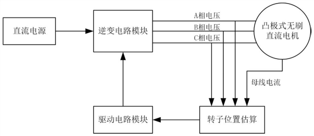
[0052] Such as figure 1 As shown, the rotor position detection system of the sensorless brushless DC motor of the present invention in a static state includes a DC power supply module, an inverter circuit module, a rotor position estimation module and a drive circuit module, wherein the DC power supply module supplies power to the inverter circuit module , the inverter circuit module outputs A, B, C three-phase voltages to the salient-pole brushless DC motor and the rotor position estimation module, and at the same time, the bus current output by the salient-pole brushless DC motor is also input to the rotor position estimation module, and the rotor position The estimation module outputs the estimated rotor position information to the driving circuit module, and the driving circuit module is used to drive and control the inverter circ...


PUM


Abstract

The invention discloses a rotor position detection system and method of a non-position sensor brushless direct current motor in a static state. The DC power supply module in the system supplies power to the inverter circuit module. The inverter circuit module outputs three-phase voltage to the brushless DC motor and the rotor position estimation module. At the same time, the bus current output by the brushless DC motor is also input to the rotor position estimation module. The rotor position The estimation module outputs the estimated rotor position information to the driving circuit module, and the driving circuit module is used to drive and control the inverter circuit module. The method estimates the initial position of the rotor by detecting the three-phase terminal voltage and the DC bus current when the motor is stationary, reduces the number of detection pulses required for the position detection process of the inductance method, shortens the positioning time, and thereby reduces the start-up delay. The invention not only has the characteristics of non-inductive positioning in a static state of the inductance method, but also has the advantage of short positioning time, and can be used in the production field of electric tools with the actual demand of non-reversing and fast starting of the motor.

Description

technical field [0001] The invention relates to motor control technology, in particular to a rotor position detection system and method in a static state of a brushless DC motor without a position sensor. Background technique [0002] The brushless DC motor needs to obtain the rotor position to control the operation, and the installation of the position sensor has brought many problems to the control of the brushless DC motor, such as increasing the size of the motor, and there are many external factors that interfere with the signal transmission channel. Sensitivity decreases in extreme environments, installation deviation will affect the positioning effect, etc. These problems have reduced the applicable field and scope of brushless DC motors to a certain extent. In order to overcome the shortcomings of installing position sensors, the new rotor position detection method without position sensors has become one of the popular research directions in the field of internationa...

Claims


Application Information

Patent Timeline
Patent Type & Authority Patents(China)
IPC IPC(8): H02P21/18H02P6/182H02P27/12
CPCH02P21/18H02P6/182H02P27/12
Inventor 武建飞韩睿王少杰
Owner 苏州崧崧智能控制技术有限公司
Why Eureka
Try Eureka