Novel vibrating diaphragm

A new type of peripheral technology, applied in the field of loudspeakers, can solve the problems of insufficient amplitude of the U-shaped track ring and cannot meet the requirements of acoustic effects, and achieve high-amplitude effects

Inactive Publication Date: 2020-11-13
RUISHENG NEW ENERGY DEV CHANGZHOU
View PDF8 Cites 0 Cited by
  • Summary
  • Abstract
  • Description
  • Claims
  • Application Information

AI Technical Summary

Problems solved by technology

With the improvement of product quality requirements, one design idea is to reduce the width of the U-shaped runway ring, that is, to limit the overall width of the U-shaped runway ring to a smaller range, but based on the same material, this The adjustment of the structural specifications will cause the U-shaped runway ring to have insufficient amplitude in actual use and cannot meet the corresponding acoustic effect requirements

Method used


Image

  • Novel vibrating diaphragm
  • Novel vibrating diaphragm
  • Novel vibrating diaphragm

Examples


Embodiment Construction

[0020] The present invention will be further described below in conjunction with the accompanying drawings and embodiments.

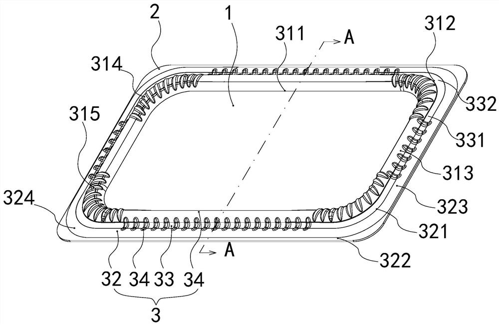
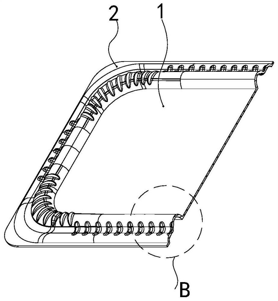
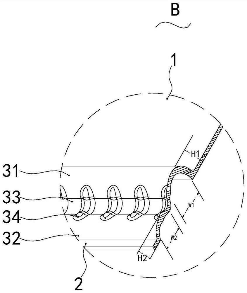
[0021] Such as Figure 1-Figure 3 As shown, a new type of diaphragm has a central part 1, a peripheral part 2 and a ring part 3 connecting the central part 1 and the peripheral part 2. The ring part 3 includes a first ring 31, a second ring 32 and a connection The first ring 31 and the second ring 32 are located at the connecting portion 33 between them, the first ring 31 includes a first edge end 311 connected to the central portion 1 and a second edge end connected to the connecting portion 33 312 ; the second ring 32 includes a first peripheral end 321 connected to the connecting portion 33 and a second peripheral end 322 connected to the peripheral portion 2 ; the first ring 31 and the second ring 32 bulge in the same direction.

[0022] In the basic solution of the present invention, the central part 1 of the diaphragm is generally connected to th...


PUM


Abstract

The invention provides a novel vibrating diaphragm. The vibrating diaphragm comprises a central part, a peripheral part and a folding ring part connected with the central part and the peripheral part,the vibrating diaphragm is characterized in that the folding ring part comprises a first folding ring, a second folding ring and a connecting part which is connected with the first folding ring and the second folding ring and located between the first folding ring and the second folding ring, and the first folding ring comprises a first edge end connected with the center part and a second edge end connected with the connecting part; the second folding ring comprises a first peripheral end connected with the connecting part and a second peripheral end connected with the peripheral part; and the first folding ring and the second folding ring bulge towards the same direction. Compared with the vibrating diaphragm in the prior art, the vibrating diaphragm has obvious difference in structure,specifically, the folding ring part is divided into the first folding ring and the second folding ring, and the folding ring part formed by the two parts can have higher amplitude in a state that thewidth of the whole folding ring part is relatively low, so that the corresponding acoustic performance requirement is met.

Description

【Technical field】 [0001] The invention relates to the technical field of loudspeakers, in particular to a novel diaphragm. 【Background technique】 [0002] As a device that can convert electrical energy into sound energy, the speaker has been widely used in mobile terminals such as mobile phones, computers, and PADs. The performance of the speaker directly affects the sound output effect of the mobile terminal device that cooperates with it. The conventional structure of the loudspeaker generally includes a magnetic circuit system and a vibration system. The vibration system also includes a diaphragm and a voice coil. The diaphragm vibrates, and then radiates sound waves to the outside world, thereby completing the conversion of electrical energy into sound energy. It can be seen from the above description that the diaphragm is one of the key components for the speaker to vibrate and produce sound. [0003] The loudspeaker diaphragm in the prior art includes a central part ...

Claims


Application Information

Patent Timeline
IPC IPC(8): H04R7/18H04R7/22H04R9/06H04R9/02
CPCH04R7/18H04R7/22H04R9/06H04R9/02
Inventor 梁平赵彬
Owner RUISHENG NEW ENERGY DEV CHANGZHOU
Why Eureka
Try Eureka