Adjusting method of laser display equipment and laser display equipment

A laser display and adjustment method technology, applied in optics, optical components, instruments, etc., can solve the problem of display resolution drop, achieve the effect of solving display resolution drop, increasing drive current, and improving vibration loudness

Pending Publication Date: 2020-08-04
QINGDAO HISENSE LASER DISPLAY CO LTD
View PDF8 Cites 2 Cited by
  • Summary
  • Abstract
  • Description
  • Claims
  • Application Information

AI Technical Summary

Problems solved by technology

[0006] The application provides an adjustment method of a laser display device and a laser display device, which solve the technical problem that the display resolution of the existing laser display device decreases due to the aging of the vibrating mirror

Method used


Image

  • Adjusting method of laser display equipment and laser display equipment
  • Adjusting method of laser display equipment and laser display equipment
  • Adjusting method of laser display equipment and laser display equipment

Examples


Embodiment Construction

[0018] The specific implementation manners of the present application will be described in further detail below in conjunction with the accompanying drawings.

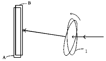
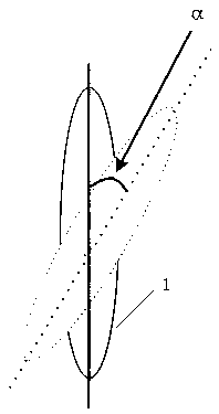
[0019] The adjustment method of the laser display device proposed by this application is based on such as Figure 4 The laser display device shown is realized. The laser display device includes a vibrating mirror 1, a sound sensor 2, a vibration loudness determination module 3 and a vibrating mirror driving module 4; the vibrating mirror driving module 4 is used to drive the vibrating mirror to vibrate according to a set frequency; the sound The sensor 2 is arranged around the vibrating mirror 1 according to a set distance, and is used to detect the sound signal from the vibrating mirror 1; the vibration loudness determination module 3 is used to obtain the sound signal from the vibrating mirror detected by the sound sensor 2, and determine the sound signal of the vibrating mirror based on the sound signal. The vibrati...


PUM


Abstract

The invention discloses an adjusting method of laser display equipment and the laser display equipment. A sound sensor is arranged on the periphery of a galvanometer, the sound sensor detects a soundsignal sent by the galvanometer, the system determines the vibration loudness of the galvanometer based on the sound signal, and when the determined vibration loudness of the galvanometer is lower than a set threshold value, the driving voltage of the galvanometer is adjusted so as to enable the vibration loudness of the galvanometer to reach the set threshold value. The vibration loudness of thegalvanometer is determined by the amplitude of the galvanometer; if the detected vibration loudness is reduced, the impedance of a driving coil is increased due to aging of a driving coil, and the vibration amplitude of the galvanometer is reduced; if the amplitude is reduced, the deflection angle of the galvanometer is reduced; and the vibration loudness of the galvanometer is adjusted to be consistent with the set threshold value at the moment by adjusting the driving voltage of the galvanometer, and it is guaranteed that the deflection angle of the galvanometer is not reduced, so that the display resolution is guaranteed, and the technical problem that the display resolution of existing laser display equipment is reduced due to galvanometer aging is solved.

Description

technical field [0001] The invention belongs to the technical field of laser display, and in particular relates to a method for adjusting a laser display device and the laser display device. Background technique [0002] Most laser TVs use the DLP (Digital Light Processing, digital light processing) solution. At present, this solution cannot achieve 4K display effect. To achieve 4K resolution of the screen, a key device-galvanometer is required. The vibrating mirror is an optical device that can vibrate in one or several axes by using a voltage drive. Its function is to change the transmission direction of the light beam passing through it, thereby improving the resolution. [0003] The vibrating mirror is located between the light valve and the lens. It is a flat glass or a mirror, which can transmit or reflect the image beam. The vibration of the galvanometer makes the image beams corresponding to two adjacent frames of projection images passing through the galvanometer n...

Claims


Application Information

Patent Timeline
IPC IPC(8): G02B26/08G03B21/20
CPCG02B26/0858G03B21/2066
Inventor 李征
Owner QINGDAO HISENSE LASER DISPLAY CO LTD
Why Eureka
Try Eureka