
Z-shaped elastic flange structure for ultrasonic transducer and application of Z-shaped elastic flange structure

An ultrasonic transducer and elastic technology, applied in cleaning methods using liquids, fluids using vibration, chemical instruments and methods, etc., can solve problems such as node position deviation, inaccurate setting of flanges, etc. Amplitude effect

Pending Publication Date: 2021-08-24
深圳市智博超声科技有限公司
View PDF0 Cites 0 Cited by
  • Summary
  • Abstract
  • Description
  • Claims
  • Application Information

AI Technical Summary

Problems solved by technology

However, due to the errors in the processing and manufacturing of transducer parts, the flange cannot be accurately set on the joint surface. In addition, the transducer is affected by various boundary conditions during work, which will cause a slight deviation in the position of the joint surface. At the same time, the flange structure inevitably has a certain thickness. This series of reasons lead to the inevitable occurrence of longitudinal coupling.

Method used

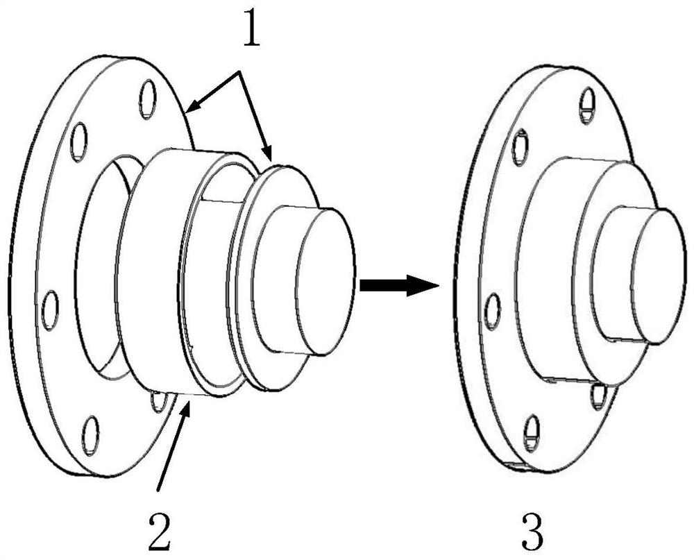
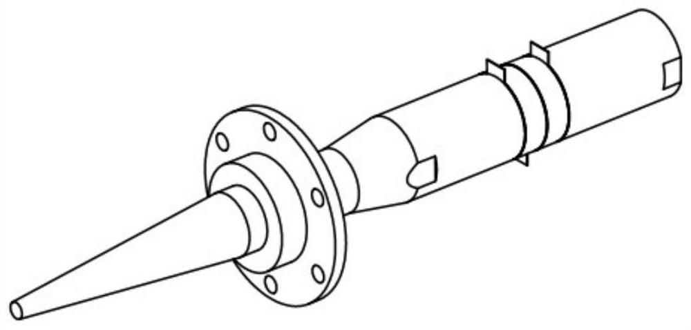

Image

  • Z-shaped elastic flange structure for ultrasonic transducer and application of Z-shaped elastic flange structure
  • Z-shaped elastic flange structure for ultrasonic transducer and application of Z-shaped elastic flange structure
  • Z-shaped elastic flange structure for ultrasonic transducer and application of Z-shaped elastic flange structure

Examples


Embodiment 1

[0039] The modal analysis and calculation are carried out for the ultrasonic transducer with a plane flange at the joint surface and the ultrasonic transducer with a Z-shaped elastic flange structure, and the respective mode shapes within half a cycle around the flange are obtained.

[0040] Such as Figure 6As shown, the modal analysis results of the ultrasonic transducer with a flat flange and the ultrasonic transducer with a Z-shaped elastic flange structure are respectively listed in the upper and lower boxes. The traditional flat flange and the Z-shaped elastic flange The respective positions and postures at three different moments within half a cycle (0.1T ~ 0.5T) of structural vibration. From Figure 6 In (a), it can be seen that when the vibration of the ultrasonic transducer body occurs, the planar flange structure is excited to shrink and expand in the radial direction, such as Figure 6 As shown by the arrow in (a). Due to the rigid fixation of the traditional pl...

Embodiment 2

[0042] The ultrasonic transducer was driven by a sinusoidal electrical signal with a voltage value of 40V, and the amplitude of the ultrasonic transducer was investigated. In order to avoid the impact of ultrasonic transducer heating on its vibration characteristics due to long-term work, each excitation time is only 0.02s. When two ultrasonic transducers with different flange structures are driven by their respective resonant frequencies (corresponding to 40V voltage value), their amplitudes are recorded, as Figure 7 Shown in ① and ②. Considering that the ultrasonic transducer is susceptible to changes in the external environment when it is working, the resonant frequency is also changed accordingly. Therefore, if the actual resonant frequency of the ultrasonic transducer deviates from the applied excitation frequency, the ultrasonic transducer will be detuned. Working in the state, and at the same time, the position of the nodal surface changes to a certain extent, and the...


PUM


Abstract

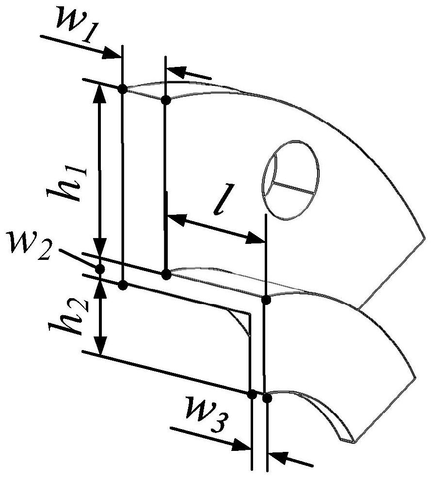
The invention discloses a Z-shaped elastic flange structure and application thereof. The Z-shaped elastic flange structure can reduce the leakage of ultrasonic energy from a flange to the outside when an ultrasonic transducer works, and improve the vibration performance and stability of the ultrasonic transducer. The structure comprises a plane flange part and an elastic cylindrical ring part, wherein the plane flange part and the elastic cylindrical ring part are combined together, and the section is in a Z shape; the plane flange part has a first radial length h1 and a first thickness w1; and the elastic cylindrical ring part has a second radial length h2, a second thickness w2, a third thickness w3 and a cylindrical ring length l. Longitudinal coupling and radial coupling can be reduced, and the end face amplitude of the ultrasonic transducer is greatly improved. No matter whether the ultrasonic transducer works in a resonance state or not, the Z-shaped elastic flange structure can remarkably improve the amplitude of the ultrasonic transducer. Compared with a traditional face flange, during resonance, the Z-shaped elastic flange structure can improve the amplitude by 15.3%, and the rigidity of the ultrasonic transducer for bearing external force is not lost.

Description

technical field [0001] The invention relates to the technical field of ultrasonic transducers, in particular to a Z-shaped elastic flange structure for ultrasonic transducers and its application. Background technique [0002] Piezoelectric ultrasonic transducer is one of the most important core components in the field of modern power ultrasonic, it is responsible for converting electrical energy into ultrasonic mechanical vibration, and then transmits the vibration to the tool head installed at its end. For example, in ultrasonic surgical equipment, ultrasonic transducers generate ultrasonic vibrations and transmit them to surgical knives installed at the end, and surgical knives use ultrasonic vibrations to remove biological tissues; in microelectronic thermosonic welding, ultrasonic transducers It converts electrical energy into ultrasonic vibrations of a soldering tool mounted on its end, and then establishes a reliable electrical connection between the integrated circuit...

Claims


Application Information

Patent Timeline
IPC IPC(8): B06B1/06B08B3/12B08B13/00A61B17/16A61B17/32
CPCA61B17/16A61B17/320068A61B2017/320074B06B1/06B08B3/12B08B13/00
Inventor 吴曦张莹
Owner 深圳市智博超声科技有限公司
Learn More