Scalpel rod structure and ultrasonic scalpel including scalpel rod structure

A knife rod and coarse structure technology, applied in the field of ultrasonic scalpel, can solve the problems of endangering the personal safety of patients, affecting the effect of surgery, easy to receive external interference and load effect, etc., and achieve the effect of improving power conversion efficiency and amplitude enhancement

Active Publication Date: 2019-12-17
HARBIN INST OF TECH
View PDF9 Cites 2 Cited by
  • Summary
  • Abstract
  • Description
  • Claims
  • Application Information

AI Technical Summary

Problems solved by technology

[0002] Clinically, the ultrasonic scalpel has very good effects, such as: neat knife edge, fast hemostasis, small thermal damage range, less smoke, etc., and has now become an important tool for clinical surgery. The requirements for the scalpel are getting higher and higher. These problems are mainly manifested in the fact that the ultrasonic scalpel is easy to receive external interference and load during the working process, and it is easy to change its vibration mode from pure longitudinal vibration to other vibrations. mode, thus affecting the working efficiency and cutting ability of the ultrasonic scalpel, thus causing certain difficulties for clinicians in the precise control of the scalpel, which in turn affects the surgical effect and even endangers the personal safety of patients. The traditional ultrasonic scalpel cannot solve the problem gradually. these needs

Method used


Image

  • Scalpel rod structure and ultrasonic scalpel including scalpel rod structure
  • Scalpel rod structure and ultrasonic scalpel including scalpel rod structure
  • Scalpel rod structure and ultrasonic scalpel including scalpel rod structure

Examples


Embodiment Construction

[0024] It should be noted that the embodiments of the present invention and the features in the embodiments can be combined with each other if there is no conflict.

[0025] Hereinafter, the present invention will be described in detail with reference to the drawings and in conjunction with the embodiments.

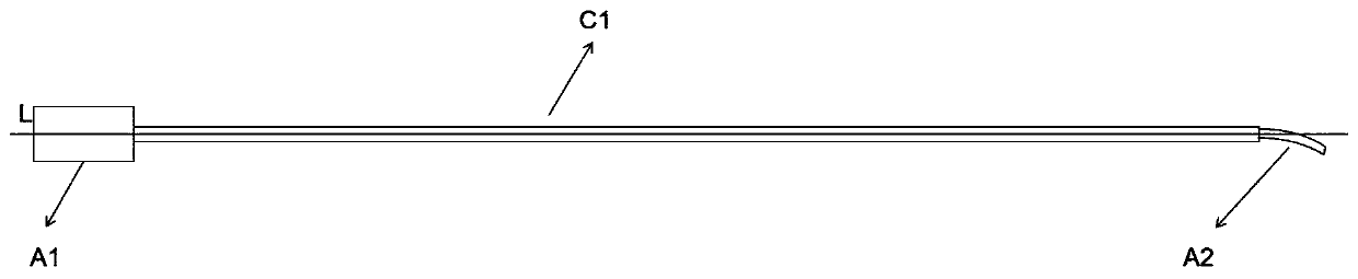
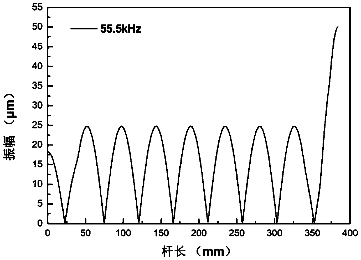
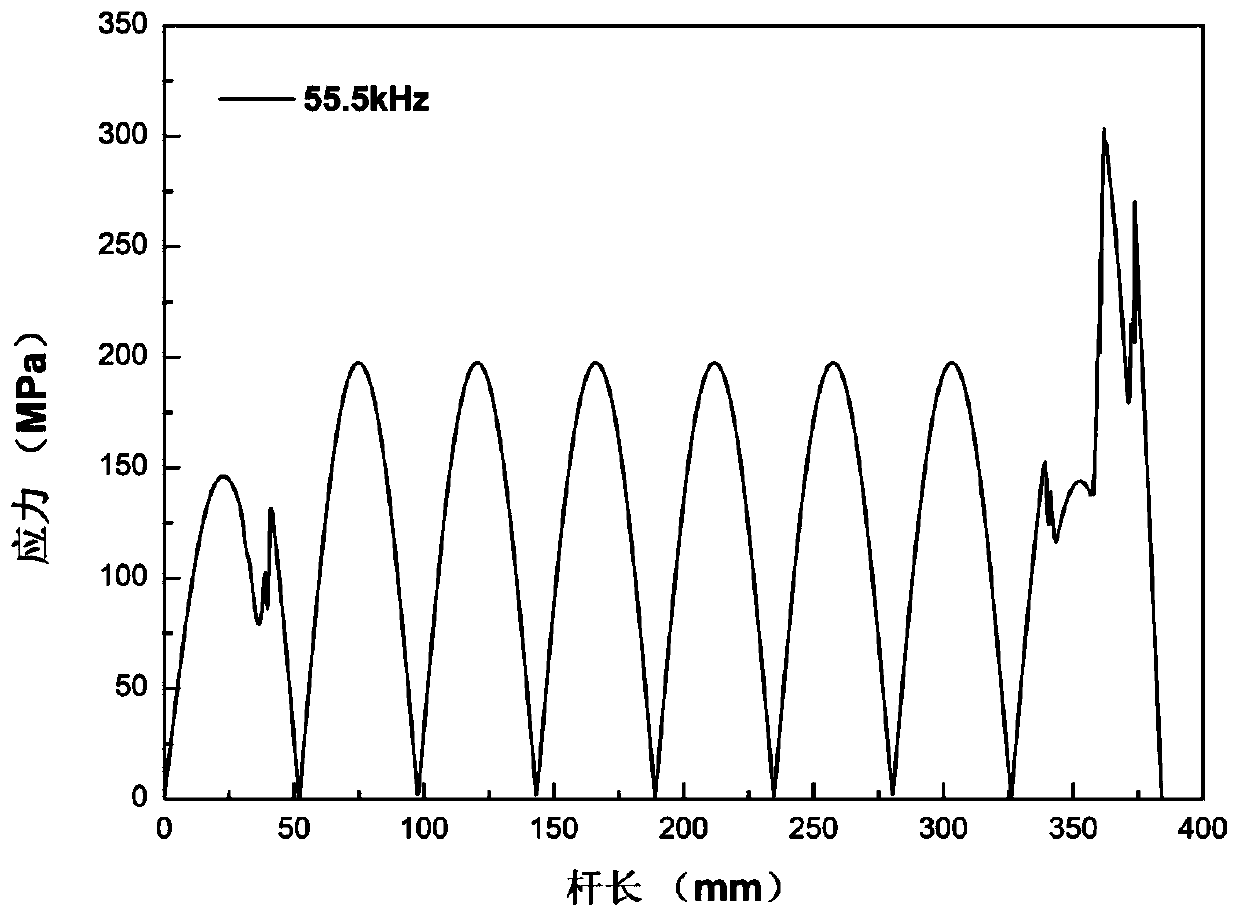
[0026] Such as figure 1 Shown is an existing ultrasonic scalpel, which has a tail, a slender shaft and a blade head. The amplitude diagram and stress diagram of the existing ultrasonic scalpel at a fixed frequency of 55.5kHz are as follows figure 2 with image 3 Shown. The length of the slender shaft of the existing ultrasonic scalpel is 320.7 mm, the length of the tail is 22.8 mm, and the length of the blade is 23.5 mm.

[0027] Such as Figure 4 As shown, an ultrasonic scalpel includes a shank structure and a cutter head A2 with a total length of 367mm, wherein the length of the shank structure is 343.5mm, and the length of the cutter head A2 is 23.5mm. The shank structure in...


PUM

PropertyMeasurementUnit
Lengthaaaaaaaaaa
Diameteraaaaaaaaaa
Lengthaaaaaaaaaa

Abstract

The invention provides a scalpel rod structure and an ultrasonic scalpel including the scalpel rod structure. The length of the scalpel rod structure is 343.5 mm. The scalpel rod structure comprises atail part, a coupling area I, a coarse-fine alternate area and a coupling area II, wherein the tail part, the coupling area I, the coarse-fine alternate area and the coupling area II are sequentiallyconnected. The coarse-fine alternate area is formed by alternately arranging cylinders with different diameters. The tail part is a cylinder body. The coupling area I is a cylinder body. The couplingarea II is a cylinder body. The coarse-fine alternate area is provided with six fine structures and six coarse structures. All the coarse structures have the same diameter. All the fine structures have the same diameter, and the diameter difference between the coarse structures and the fine structures is less than 0.3mm. The coupling area I is connected with the fine structures in the coarse-finealternate area, and the coupling area II is connected with the coarse structures in the coarse-fine alternate area. The ultrasonic scalpel can work safely in a fixed frequency range without causing difficulty in operation or unsafe use due to frequency drift; and when an ultrasound wave passes through the coarse-fine alternate structure, the amplitude of an ultrasonic scalpel head can be enhanced, and the electrical energy conversion efficiency can be improved.

Description

Technical field [0001] The invention belongs to the field of ultrasonic medical treatment, and in particular relates to a knife bar structure and an ultrasonic scalpel containing the knife bar structure. Background technique [0002] In clinical practice, ultrasonic scalpel has very good effects, such as: neat cutting edge, fast hemostasis, small thermal damage range, less smoke, etc. It has now become an important tool for clinical surgery. With the continuous development of technology, ultrasound The requirements for scalpels are also getting higher and higher. These problems are mainly manifested in the fact that ultrasonic scalpels are prone to external interference and load effects during the work process, and it is easy to change the vibration mode from pure longitudinal vibration to other vibrations. Modal, which affects the working efficiency and cutting ability of the ultrasonic scalpel, which causes certain difficulties for the clinician to control the scalpel accuratel...

Claims


Application Information

Patent Timeline
IPC IPC(8): A61B17/32
CPCA61B17/320068
Inventor 刘丹青杨彬吴亚南
Owner HARBIN INST OF TECH
Why Eureka
Try Eureka