Supercharge Your Innovation With Domain-Expert AI Agents!

Decorative light source shielding

A light source device, periodic technology, applied in the field of illuminators, manufacturing this kind of body, can solve unpleasant problems

Active Publication Date: 2020-11-13
SIGNIFY HLDG BV
View PDF8 Cites 0 Cited by
  • Summary
  • Abstract
  • Description
  • Claims
  • Application Information

AI Technical Summary

Problems solved by technology

This may be to improve the aesthetic appearance of the light source, as well as to avoid glare when viewing such a light source directly, which may be unpleasant and even cause headaches or similar medical problems

Method used


Image

  • Decorative light source shielding
  • Decorative light source shielding
  • Decorative light source shielding

Examples


Embodiment Construction

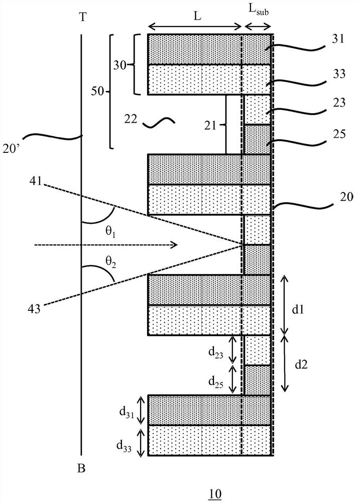
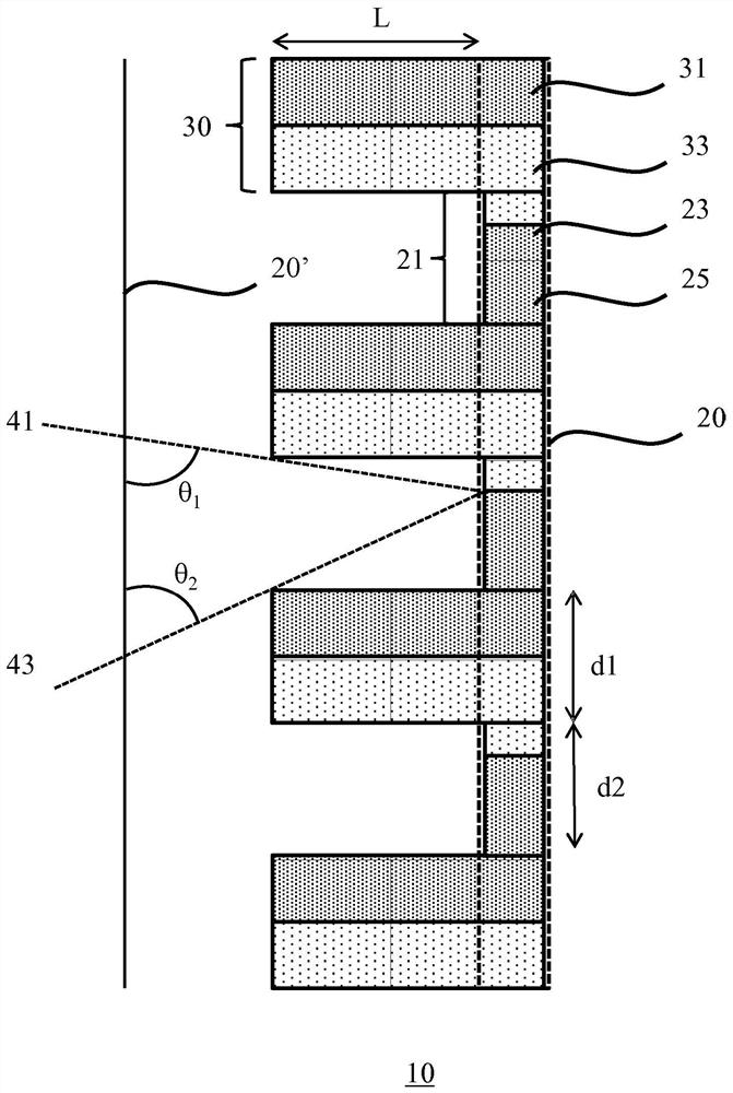
[0033] It should be understood that the drawings are only schematic and not drawn to scale. It should also be understood that throughout the drawings, the same reference numerals are used to indicate the same or similar parts.

[0034] In the context of this application, where reference is made to optical reflectivity, this refers to the degree of reflection of a material with respect to light of a certain spectral composition, such as visible light. When referring to a difference in optical reflectivity, this may refer to a difference in reflectivity, and includes embodiments where the difference in optical reflectivity between different parts of the body of the present invention means that one of the parts is in Optically it is highly reflective, while the rest of the part is less reflective. Different optical reflectivities may also refer to different reflectivities of light having a particular spectral composition, such as different reflectivities for different spectral c...


PUM


Abstract

A body (10) is disclosed for obscuring a light source arrangement (3). The body comprises a surface (20) including a plurality of optically reflective relief structures (30, 30', 30"), each relief structure comprising a first portion (31) and a second portion (33) adjacent to said first portion extending from said surface, wherein the first portion has a different optical reflectivity to the second portion and neighboring optically reflective relief structures are separated by an optically transparent medium contacting said neighboring optically reflective relief structures. Also disclosed isa luminaire comprising such a body and a method of manufacturing such a body.

Description

technical field [0001] The invention relates to a body used for shielding a light source device. [0002] The invention also relates to a luminaire comprising such a body and a light source device. [0003] The invention also relates to a method of manufacturing such a body. Background technique [0004] It is desirable to conceal light sources such as incandescent light sources, fluorescent light sources, halogen light sources, solid state light sources (eg LEDs), etc. from direct view. This may be to improve the aesthetic appearance of the light source, as well as to avoid glare when viewing such a light source directly, which may be unpleasant and even cause headaches or similar medical problems. [0005] For this reason, the light source is usually hidden from direct view by an optically reflective body which modifies the luminous distribution of the light source, for example by diffusing this luminous distribution or changing its intensity and / or spectral composition....

Claims


Application Information

Patent Timeline
Patent Type & Authority Applications(China)
IPC IPC(8): F21V1/12F21V9/40F21V1/26
CPCF21V1/12F21V1/26F21V9/40B29C64/118B33Y10/00B33Y80/00B29L2031/7472F21V1/22
Inventor R·A·M·希克梅特P·A·范哈尔
Owner SIGNIFY HLDG BV
Features
  • R&D
  • Intellectual Property
  • Life Sciences
  • Materials
  • Tech Scout
  • Unparalleled Data Quality
  • Higher Quality Content
  • 60% Fewer Hallucinations
Learn More