refrigeration refrigerator
A technology for refrigerators and heaters, which is applied to household refrigeration devices, defrosting, lighting and heating equipment, etc. It can solve the problems of difficult heater laying to the lower end, increase the degree of freedom, realize thinner diameters, and suppress the electrification rate the increased effect of
- Summary
- Abstract
- Description
- Claims
- Application Information
AI Technical Summary
Problems solved by technology
Method used
Image
Examples
Embodiment approach 1
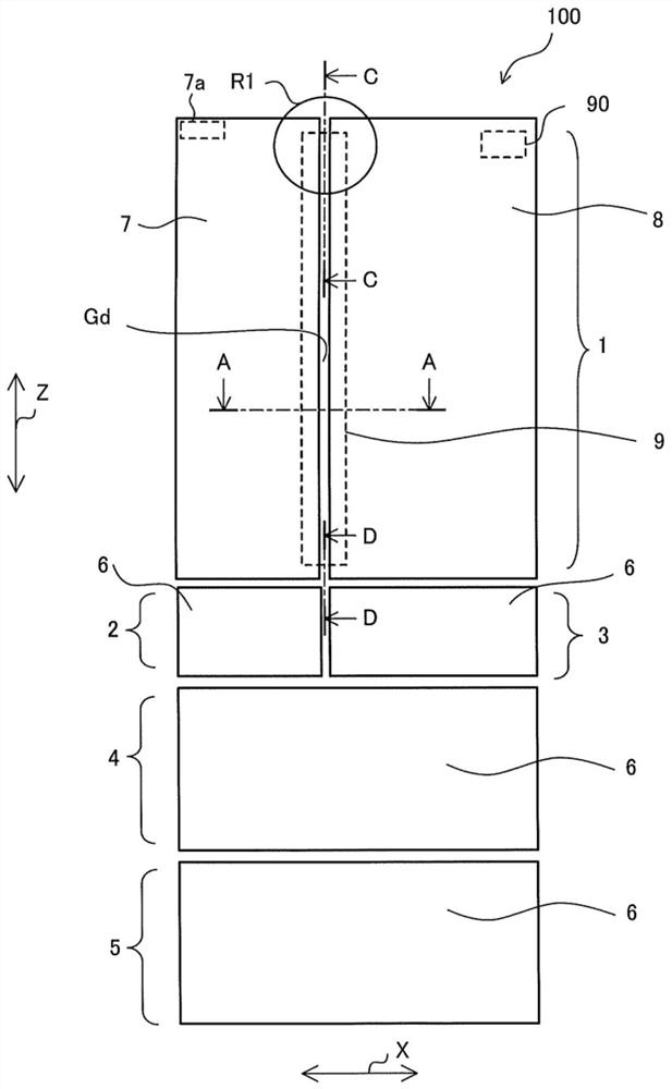
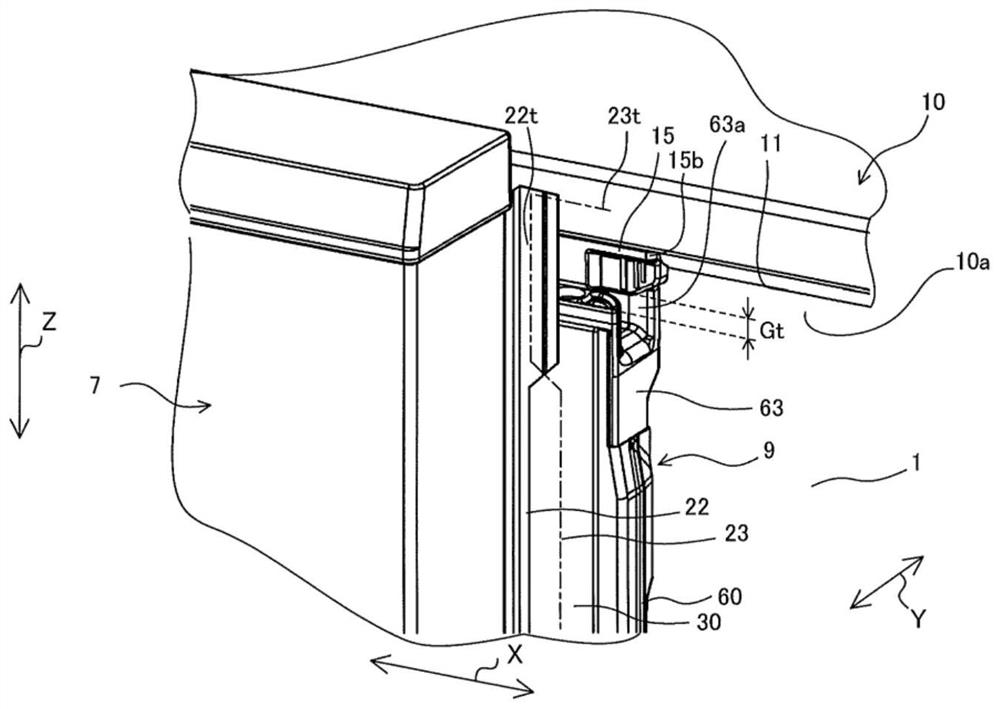
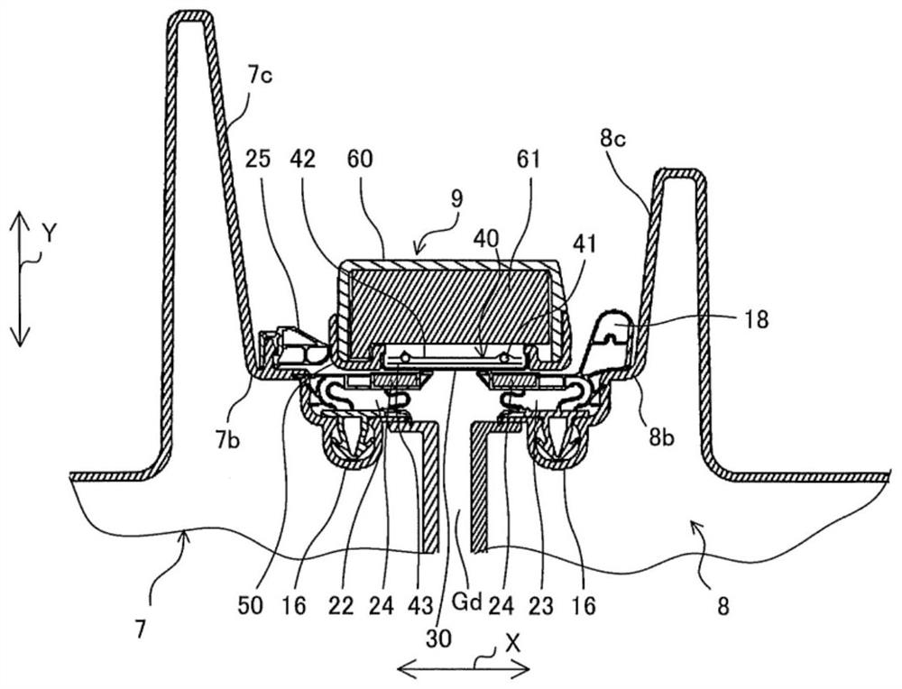
[0028] figure 1 It is a front view of a refrigerator according to an embodiment of the present invention relates. figure 2 Mean figure 1 An upper rear perspective view of a region R1 right door opened. image 3 Mean figure 1 Sectional view A-A cross section. based on Figure 1 ~ 3 , Of the schematic structure of the refrigerator 100 will be described. Indicates the width direction of the arrow X direction of the refrigerator 100, the arrow Y direction indicates the depth direction of the refrigerator 100, the direction of arrow Z indicates the height direction of the refrigerator 100.
[0029] Refrigerator includes a refrigerator main body 100 of the box-shaped front surface of the opening 10, the door opening and a plurality of plugging portions 10 of the refrigerator main body 10a. The refrigerator main body 10 to form the outline of the refrigerator 100 by the outer box and the inner box (not shown) as a cabinet, the space between the outer box and the inner box is filled with f...
Embodiment approach 2
[0090] Figure 15 It is a schematic diagram showing an insulating layer structure of a heater unit according to Embodiment 2 of the present invention. In the second embodiment, the insulating configuration of the heater unit 140 is different from the case of the first embodiment. To maintain the insulation resistance, it is necessary to ensure the degree of freedom of the heater configuration, and change the insulation pattern. Unlike the case of the first embodiment. Further, in the present embodiment, in particular, the same reference numerals are described, and the same reference numerals are described using the same reference numerals in the same manner as in the first embodiment.
[0091] For the heater 141, three resistance lines 172 are wound around the core wire 171 and coated by the base insulating layer 173, and the base insulating layer 173 is covered by an additional insulating layer 174. In Embodiment 2, the second layer additional insulating layer is formed of an ins...
Embodiment approach 3
[0097] Figure 16 It is a schematic diagram showing an insulating layer structure of a heater unit according to Embodiment 3 of the present invention. In the third embodiment, the insulating structure of the heater unit 240 is different from the case of the first embodiment. Further, in the third embodiment, in particular, the unmetrified items are also described in the same, and the same reference numerals are described in the same functions and structures.
[0098] For the heater 241, the three resistance lines 272 are wound around the core line 271 and coated with an additional insulating layer 274, and the additional insulating layer 274 is further coated by an additional insulating layer 275. Here, each of the resistance lines 272 wound around the core line 271 is covered by the base insulating layer 273. Since the resistance line 272 is fine, it is difficult to form the base insulating layer 273 by extrusion molding. In this case, the base insulating layer 273 can be coated ...
PUM
 Abstract
Description
Claims
Application Information
 - R&D
- Intellectual Property
- Life Sciences
- Materials
- Tech Scout
- Unparalleled Data Quality
- Higher Quality Content
- 60% Fewer Hallucinations
Browse by: Latest US Patents, China's latest patents, Technical Efficacy Thesaurus, Application Domain, Technology Topic, Popular Technical Reports.
© 2025 PatSnap. All rights reserved.Legal|Privacy policy|Modern Slavery Act Transparency Statement|Sitemap|About US| Contact US: help@patsnap.com


