Auxiliary positioning instrument for radiotherapy

A radiation therapy and locator technology, which is applied in radiation therapy, treatment, X-ray/γ-ray/particle irradiation therapy, etc., can solve the problem of prolonging the treatment time and achieve the effect of positioning accuracy

Pending Publication Date: 2020-11-17
ZIGONG NO 4 PEOPLES HOSPITAL
View PDF3 Cites 1 Cited by
  • Summary
  • Abstract
  • Description
  • Claims
  • Application Information

AI Technical Summary

Problems solved by technology

[0003] Since the radiation focus of the treatment cabin is fixed, only one target point can be irradiated at a time. After one target point is irradiated, the patient must be withdrawn, the protective door is closed, the head frame is re-adjusted, and the next target point is moved to th

Method used


Image

  • Auxiliary positioning instrument for radiotherapy
  • Auxiliary positioning instrument for radiotherapy
  • Auxiliary positioning instrument for radiotherapy

Examples


Embodiment 1

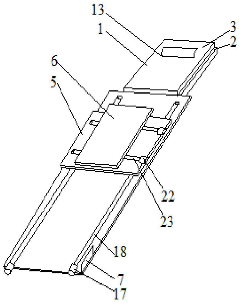
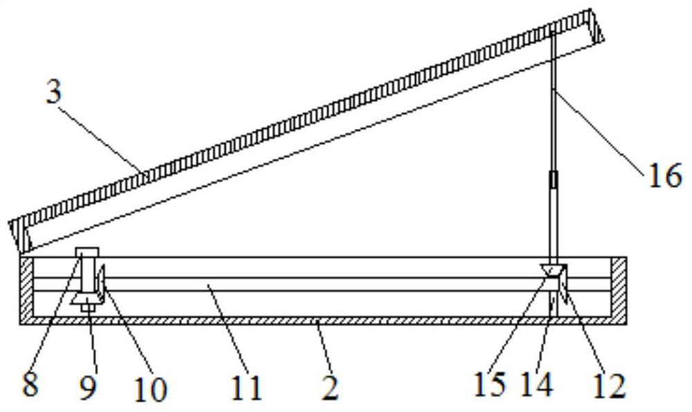
[0028] An auxiliary positioning device for radiation therapy, such as Figure 1-Figure 2 As shown, it includes a headrest 1. The headrest 1 includes a fixed plate 2 and a lifting plate 3. The lifting plate 3 is located above the fixed plate 2. One end of the fixed plate 2 and the lifting plate 3 is hingedly connected. Between the fixed plate 2 and the lifting plate 3 It is provided with a lifting mechanism, and the other end of the lifting plate 3 can be lifted along with the lifting mechanism; it also includes a base plate 4, which is a long strip structure, and is fixedly connected with the fixed plate 2; the longitudinal adjustment plate 5 slides through the first sliding assembly It is arranged on the base plate 4 and can move along the length direction of the base plate 4; there is also a horizontal adjustment plate 6, which is slid on the longitudinal adjustment plate 5 through the second slide assembly and can move along the width direction of the base plate 4; control ...

Embodiment 2

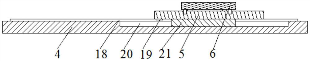
[0031] Further, on the basis of embodiment 1, such as Figure 3-4As shown, the first sliding assembly is provided with two groups, which are respectively arranged on both sides of the upper surface of the substrate 4. Each group of the first sliding assembly includes a second motor 17 arranged on the side of the substrate 4, and the output shaft of the second motor 17 is connected through the coupling. The shaft device is connected with a first screw mandrel 18, the first screw mandrel 18 is arranged along the length direction of the base plate 4, the lower surface of the longitudinal adjustment plate 5 is provided with a first slider 19, and the first slider 19 and the first screw mandrel 18 Threaded connection, the second motor 17 is connected with the control circuit; the upper surface of the substrate 4 is provided with a first fixing groove 20 along its length direction, the first fixing groove 20 is located on the outside of the first screw rod 18, and the bottom of the l...


PUM


Abstract

The invention discloses an auxiliary positioning instrument for radiotherapy. The instrument comprises a headrest; the headrest comprises a fixing plate and a lifting plate; the lifting plate is located above the fixing plate; the fixing plate is hinged to one end of the lifting plate; a lifting mechanism is arranged between the fixing plate and the lifting plate; the other end of the lifting plate can ascend and descend along with the lifting mechanism. The instrument further comprises a base plate connected with the fixing plate, a longitudinal adjusting plate arranged on the base plate in asliding mode through a first sliding assembly, a transverse adjusting plate arranged on the longitudinal adjusting plate in a sliding mode through a second sliding assembly, and a control panel. A control chip and a control circuit which are connected with each other are arranged in the control panel. The control panel is electrically connected with the lifting mechanism, the first sliding assembly and the second sliding assembly. Through the lifting mechanism, the first sliding assembly and the second sliding assembly, automatic positioning of a target position of radiotherapy in space is achieved, and finally the target position is moved to a ray focus of radiation equipment.

Description

technical field [0001] The invention belongs to the technical field of medical equipment, and in particular relates to an auxiliary positioning instrument for radiotherapy. Background technique [0002] The radiotherapy positioning device consists of a fixed treatment cabin and a three-dimensional bed, and the focus of rays in the treatment cabin is fixed. After fixing the patient with a head frame, MRI or CT scans are used to determine the location of the tumor on the patient's head, which is the target point, and then make a treatment plan for treatment. During the treatment, the patient's head frame is fixed on the bracket, and then pushed into the predetermined position of the treatment chamber, so that the focus of the treatment chamber coincides with the target point of the patient, and then the radiation is turned on for treatment. [0003] Since the radiation focus of the treatment cabin is fixed, only one target point can be irradiated at a time. After one target p...

Claims


Application Information

Patent Timeline
IPC IPC(8): A61N5/10
CPCA61N5/1069A61N2005/1057A61N2005/1097
Inventor 缪继东胡胜荣尤玮周吉祥宋怡兵郭开峰刘理波陶勇许伦李家伟谢炉峰杨丽丽詹蕊羽高扬伍海琼徐勤廖勇邓罗森管勇张晔熙徐玮张丽陈佳
Owner ZIGONG NO 4 PEOPLES HOSPITAL
Why Eureka
Try Eureka