Mixing and stirring device for plant beverages
A technology of mixing and stirring and plant beverages, which is applied in mixers, mixer accessories, transportation and packaging, etc., can solve the problems of user trouble, troublesome handling of external climbing tools, and difficulty in fixing, so as to increase friction stability and strengthen pedaling Safety, Overall Setup Simple Effects
- Summary
- Abstract
- Description
- Claims
- Application Information
AI Technical Summary
Problems solved by technology
Method used
Image

Examples
Embodiment 1
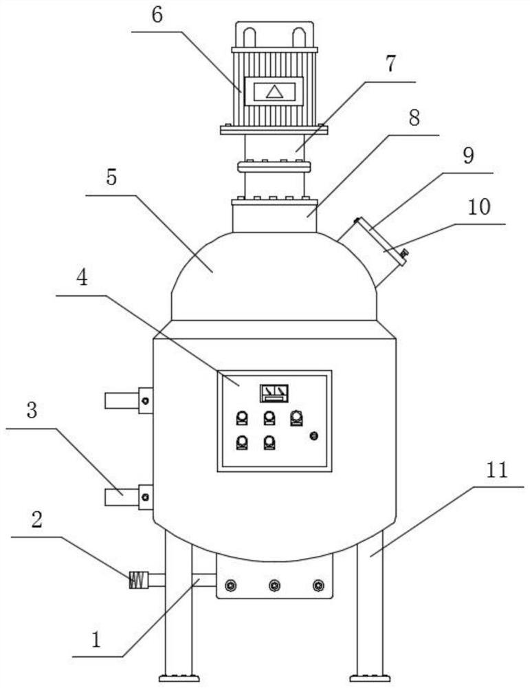
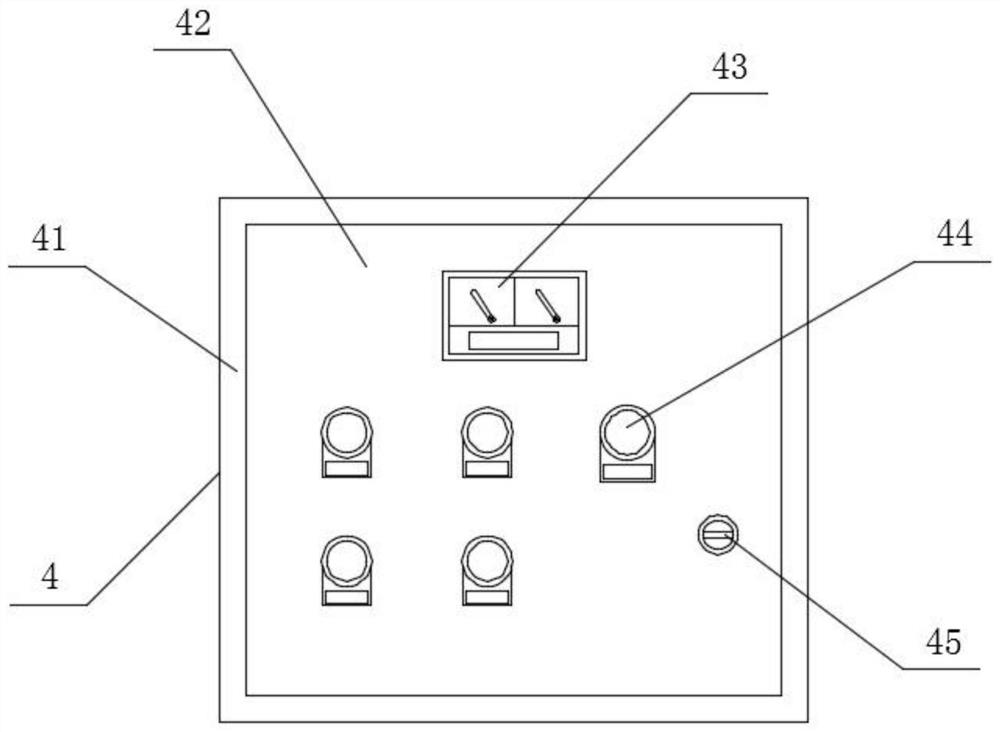
[0033] Such as Figure 1-4 As shown, a plant beverage mixing and stirring device includes a tank body 5 and an operation box 4. The front position of the outer surface of the tank body 5 is connected to the operation box 4 by welding. The operation box 4 can be electrically connected with the motor 6. The operation box 4. It includes a box body 41, an outer box door 42, a display table 43, a start switch 44 and a key hole 45. The front end surface of the box body 41 is connected with an outer box door 42, and the front end surface of the outer box door 42 is connected with a display Table 43, a start switch 44 is arranged below the display table 43, and a key hole 45 is provided at the lower right position of the start switch 44. The start switch 44 can control the opening and closing of the device as the control center of the device. A fixed bracket 11 is arranged on the right side of the bottom end surface of the tank body 5, and the bottom end surface of the fixed bracket 1...
Embodiment 2
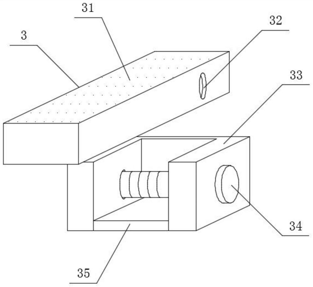
[0037] Such as Figure 1-9 As shown, a plant beverage mixing and stirring device includes a tank body 5 and an operation box 4. The front position of the outer surface of the tank body 5 is connected with the operation box 4 by welding, and the bottom of the operation box 4 is located at the bottom of the tank body 5. The right side of the end face is provided with a fixed bracket 11, and the left side of the fixed bracket 11 is provided with a conduction pipe 1. The left end face of the conduction pipe 1 is connected with a liquid outlet column 2 by welding, and the top of the liquid outlet column 2 is located on the outer surface of the tank body 5. A pedal 3 is provided at the left side position, and an observation column 10 is arranged at the upper right position of the pedal 3. The top end face of the observation column 10 is connected with an outer cover plate 9, and the top of the outer cover plate 9 is positioned at the tank body 5. The center position of the top end f...
PUM
 Abstract
Description
Claims
Application Information
 - R&D
- Intellectual Property
- Life Sciences
- Materials
- Tech Scout
- Unparalleled Data Quality
- Higher Quality Content
- 60% Fewer Hallucinations
Browse by: Latest US Patents, China's latest patents, Technical Efficacy Thesaurus, Application Domain, Technology Topic, Popular Technical Reports.
© 2025 PatSnap. All rights reserved.Legal|Privacy policy|Modern Slavery Act Transparency Statement|Sitemap|About US| Contact US: help@patsnap.com