Supercharge Your Innovation With Domain-Expert AI Agents!

Diaphragm type carburetor suitable for high-temperature state

A technology of diaphragm carburetor and high temperature state, which is applied in the direction of carburetor, machine/engine, charging system, etc., and can solve problems such as engine starting is not smooth, affecting engine use, etc.

Pending Publication Date: 2022-05-10
ZHEJIANG RUIXING CARBURETOR MFG
View PDF0 Cites 0 Cited by
  • Summary
  • Abstract
  • Description
  • Claims
  • Application Information

AI Technical Summary

Problems solved by technology

[0004] The purpose of the present invention is to provide a diaphragm type carburetor suitable for high temperature conditions, so as to solve the problem of poor engine start due to lack of fuel or less fuel in the metering chamber when the engine is started for the first time in the existing carburetor. Smooth, problems that affect the use of the engine

Method used


Image

  • Diaphragm type carburetor suitable for high-temperature state
  • Diaphragm type carburetor suitable for high-temperature state
  • Diaphragm type carburetor suitable for high-temperature state

Examples


Embodiment 1

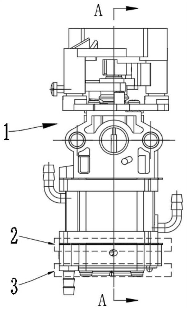
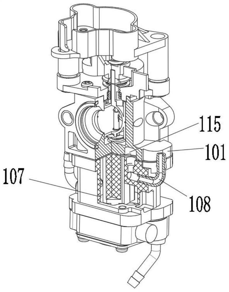
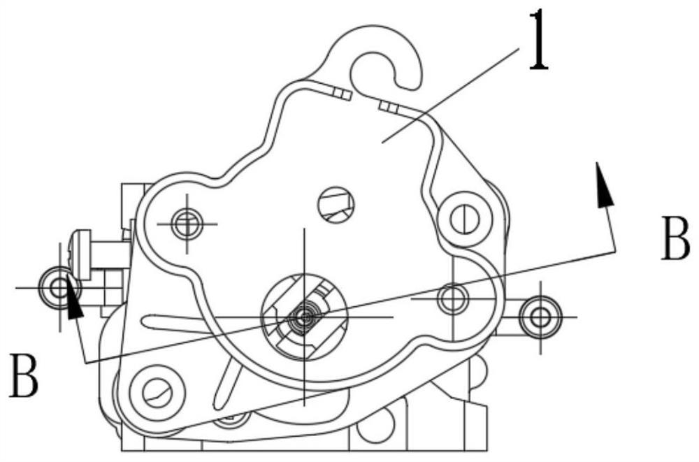
[0029] combine Figure 1~6 As shown, it schematically shows a diaphragm carburetor suitable for high-temperature conditions according to an embodiment of the present invention, including a main body 1, a diaphragm pump 2 and a metering system 3. It should be noted that in this embodiment Diaphragm pump 2 and metering system 3 all adopt the diaphragm pump 2 and metering system 3 of the existing carburetor. This embodiment does not involve improving the structure of diaphragm pump 2 and metering system 3. The main body 1 includes sequentially Connected upper body 101, heat insulating body 102, middle body 103 and lower body 104, upper body 101, heat insulating body 102, middle body 103 and lower body 104 are fixed together by screws to form a whole, diaphragm pump 2 and metering system 3. The generated fuel supply is sprayed from the main nozzle 110 through a fuel channel 109 to supply fuel to the carburetor main body 1. The upper body 101 is provided with a mixing chamber 106 c...

Embodiment 2

[0037] refer to Figure 7 ~ Figure 10 As shown, the difference between this embodiment and Embodiment 1 is that the lower end of the lower cover 302 is provided with a pump oil ball 4, and the pump oil ball 4 is connected to an oil pot through an oil circuit, and a The second one-way valve 116, the second one-way valve 116 opens and closes towards the balance pipe 108, and the function of the pump oil ball 4 is: when the engine is started, first squeeze the pump oil ball 4 by hand, because the pump oil ball 4 When squeezed, it deforms to generate vacuum suction, which sucks the fuel out of the oil pot, and the fuel from the Figure 10 The oil inlet pipe 111 in a (or b) enters, passes through the metering chamber 301 of the oil passage 1 to c, d, and e, and then passes through the oil pump ball 4 from f to g along the oil passage 2, and finally the fuel oil flows from g Return to the oil pot in the oil return pipe. After the above process, the process of sucking the fuel from ...


PUM


Abstract

The invention relates to the technical field of carburetors, and discloses a diaphragm type carburetor suitable for a high-temperature state, a heat insulation body of the carburetor is internally provided with an oil storage cavity, a metering system of the carburetor is far away from an upper body of the carburetor, and heat radiation generated when an engine works cannot be transmitted to the heat insulation body and the metering system part. The functions of the diaphragm pump and the metering system on the middle body are not affected, and normal work of the engine is guaranteed. On the other hand, due to the fact that a large oil storage space is formed in the heat insulation body, the temperature in the oil storage cavity can be taken away through transfer transition circulation of the fuel oil through the oil storage cavity, the temperature of the fuel oil in the oil storage cavity is made to be at the low temperature, and the situation that the performance of an engine is affected by air resistance generated by overheating of a metering system is avoided; and meanwhile, the metering system is ensured to have enough fuel oil for starting the engine.

Description

technical field [0001] The invention relates to the technical field of carburetors, in particular to a diaphragm carburetor suitable for high temperature conditions. Background technique [0002] The carburetor mixes a certain amount of fuel with air, and provides the required mixture according to the requirements of the engine under various operating conditions, so that the engine can run normally. In the diaphragm type carburetor of the prior art, if the engine works at high temperature for a period of time, the surface temperature of the carburetor will rise. Gasoline vapor is generated in the oil tank, which forms air resistance and affects the operation of the engine. The engine shows problems such as unstable operation or failure to start. [0003] In order to solve the above-mentioned problems, the existing technology adopts the connection between the middle body and the upper body through oil pipes to separate the two for heat transfer isolation. Less fuel in stock...

Claims


Application Information

Patent Timeline
Patent Type & Authority Applications(China)
IPC IPC(8): F02M17/04F02M19/00
CPCF02M17/04F02M19/00
Inventor 陈其安贾永成
Owner ZHEJIANG RUIXING CARBURETOR MFG
Features
  • R&D
  • Intellectual Property
  • Life Sciences
  • Materials
  • Tech Scout
  • Unparalleled Data Quality
  • Higher Quality Content
  • 60% Fewer Hallucinations
Learn More