Coaxial cable joint dismounting and mounting tool

A coaxial cable and tool technology, which is applied in the field of coaxial cable joint disassembly and assembly tools, can solve the problems of prolonging the installation and dismantling of coaxial cable joints, difficulty in plugging and unplugging coaxial cable joints, and reducing work efficiency. Significant benefit, low processing cost, and easy operation

Pending Publication Date: 2020-11-17
STATE GRID JIANGXI ELECTRIC POWER CO +1
View PDF0 Cites 0 Cited by
  • Summary
  • Abstract
  • Description
  • Claims
  • Application Information

AI Technical Summary

Problems solved by technology

However, with the continuous increase of equipment in the computer room, the coaxial cables on the digital distribution frame become more and more dense, and this manual plugging and unplugging method will bring two major problems: (1) disassembly and assembly of coaxial cables When connecting, the staff needs to insert their fingers into the middle of the cable connector to operate. The distance between the coaxial cable connectors is only 10 mm, which makes it extremely difficult for maintenance personnel to insert and insert the coaxial cable connector on a certain port, affecting Improve work efficiency: (2) During the process of plugging and unplugging the coaxial cable of a certain port, once the hand movement range is too large, it is easy to loosen the coaxial cable of the adjacent port, affecting the normal operation of the business, causing rising failure rate
The above two problems seriously prolong the time for installing and dismantling a coaxial cable connector, thereby reducing work efficiency, especially when dealing with emergency faults. Now it is urgent to develop a disassembly tool for coaxial cable connectors To solve the problems encountered in real work

Method used


Image

  • Coaxial cable joint dismounting and mounting tool
  • Coaxial cable joint dismounting and mounting tool
  • Coaxial cable joint dismounting and mounting tool

Examples


Embodiment Construction

[0014] In order to enable those skilled in the art to better understand the technical solution of the present invention, the present invention will be further described in detail below in combination with the accompanying drawings.

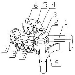
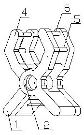
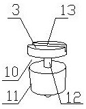
[0015] As shown in the figure, the coaxial cable connector dismounting tool includes a power mechanism, a fixing mechanism, a connecting mechanism, and a transmission mechanism. "shape, the fixing frame is respectively provided with connecting holes 2, the connecting holes are used to place the connection structure, the elastic piece 17 is arranged between the lower part of the fixed frame, the upper part of the fixed frame is provided with an arc-shaped encircling clamping arm 4, and the arc-shaped encircling The upper and lower parts on both sides of the clamping arm are respectively provided with the rotating shaft 6 of the working wheel, and the arc-shaped embracing of the outer position between the rotating shafts of the working wheel is provi...


PUM


Abstract

The invention discloses a coaxial cable joint dismounting and mounting tool. The coaxial cable joint dismounting and mounting tool comprises a power mechanism, a fixing mechanism, a connecting mechanism and a transmission mechanism, the fixing mechanism comprises fixing frames, connecting holes and arc-shaped surrounding clamping arms are arranged on the fixing frames correspondingly, working wheel rotating shafts are arranged on the two sides of the arc-shaped surrounding clamping arms correspondingly, and turning wheel rotating shafts are arranged between the working wheel rotating shafts; the connecting structure comprises an upper connector and a lower connector, the upper connector and the lower connector are connected through a driving wheel rotating shaft, a driving wheel containinggroove is formed between the upper connector and the lower connector, and a transmission groove is formed in the upper end of the upper connector; and the transmission mechanism comprises a driving wheel, turning wheels and working wheels, the driving wheel, the working wheels and the turning wheels are in friction contact, and the working wheels can be tangent to coaxial cable connectors at thesame time. The tool has the beneficial effects of being easy and convenient to operate, low in safety risk, high in accuracy, low in machining cost and easy to popularize.

Description

technical field [0001] The invention relates to the technical field of power cable operation and maintenance auxiliary tools, in particular to a coaxial cable connector disassembly tool. Background technique [0002] Coaxial cable refers to a cable with two concentric conductors, and the conductor and shield share the same axis. In the daily maintenance and maintenance process of the computer room, it is often necessary to plug and unplug the coaxial cable connector (2M cable connector) on the equipment and the digital distribution frame (DDF frame). It's all done by hand. However, with the continuous increase of equipment in the computer room, the coaxial cables on the digital distribution frame become more and more dense, and this manual plugging and unplugging method will bring two major problems: (1) disassembly and assembly of coaxial cables When connecting, the staff needs to insert their fingers into the middle of the cable connector to operate. The distance between...

Claims


Application Information

Patent Timeline
Patent Type & Authority Applications(China)
IPC IPC(8): B25B27/14
CPCB25B27/14
Inventor 肖振华江天山衷国瑛钟志萍郑琼玲丁波程鹏飞
Owner STATE GRID JIANGXI ELECTRIC POWER CO
Why Eureka
Try Eureka