Wire-blocking structure and its application to achieve stiffness variation by frictional coupling between thin wires
A technology of changing stiffness and thin lines, applied in the field of online blocking structure, can solve the problems of increasing the stiffness of the software driver, and achieve the effect of stable driving effect and improved stiffness.
- Summary
- Abstract
- Description
- Claims
- Application Information
AI Technical Summary
Problems solved by technology
Method used
Image
Examples
Embodiment 1
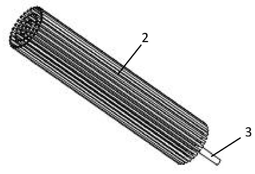
[0054] See attached figure 1 And attached figure 2 , the embodiment of the present invention discloses a wire blocking structure that utilizes frictional coupling between thin wires to realize stiffness changes, including a flexible sealing film sleeve 1 and a plurality of nylon filaments 2 coaxially filled inside the flexible sealing membrane sleeve 1 ; One end of the flexible sealing film sleeve 1 has a trachea 3 for pumping or inflating.
[0055] In order to further optimize the above technical solution, the flexible sealing film sleeve 1 is a cylindrical structure or a flat strip structure.
[0056] See attached Figure 5 , paste at least one line blocking structure on one side of the twist limiting layer 51 of the twist soft actuator 5 .
[0057] See attached Figure 9 Firstly, the torsion software driver 5 is inflated and pressurized, and the pressure is 20KPa. After the inflation is completed, the torsion software driver 5 is deformed and twisted. Then vacuumize t...
Embodiment 2
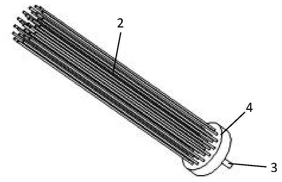
[0060] See attached image 3 , the embodiment of the present invention discloses a wire blocking structure that utilizes frictional coupling between thin wires to realize stiffness changes, including a flexible sealing film sleeve 1 and a plurality of nylon filaments 2 coaxially filled inside the flexible sealing membrane sleeve 1 ; One end of the flexible sealing film sleeve 1 has a trachea 3 for pumping or inflating;
[0061] In order to further optimize the above technical solution, the flexible sealing film sleeve 1 is a cylindrical structure or a flat strip structure.
[0062] See attached Figure 6 , paste at least one line blocking structure on one side of the bending limiting layer 61 of the bending soft driver 6 .
[0063] See attached Figure 8 First, inflate and pressurize the bending soft driver 6 with a pressure of 30KPa. After the inflation is completed, the bending soft driver 6 is deformed for bending. Then vacuumize the flexible sealing film sleeve 1, and ...
Embodiment 3
[0065] See attached Figure 10 to attach Figure 12 , this embodiment is improved on the basis of embodiment 2:
[0066] as attached Figure 10 As shown, the inflation pressure of 10KPa, 20KPa, and 30KPa is respectively applied to the bending soft driver 6, and the deformation is as follows: Figure 10 shown from left to right.
[0067] as attached Figure 11 As shown, after pasting two sections of wire blocking structure on the bending limiting layer 61 of the bending soft driver 6, and vacuumizing the wire blocking structure, the Figure 10 The bending software driver 6 in releases the pressure, and the shaping situation is as follows Figure 11 shown from left to right. Ensure that different line blocking structures have different lengths and / or vacuum levels.
[0068] as attached Figure 12 As shown, after pasting the three-section line blocking structure on the bending limiting layer 61 of the bending soft driver 6, and vacuumizing the line blocking structure, the...
PUM
 Abstract
Description
Claims
Application Information
 - R&D
- Intellectual Property
- Life Sciences
- Materials
- Tech Scout
- Unparalleled Data Quality
- Higher Quality Content
- 60% Fewer Hallucinations
Browse by: Latest US Patents, China's latest patents, Technical Efficacy Thesaurus, Application Domain, Technology Topic, Popular Technical Reports.
© 2025 PatSnap. All rights reserved.Legal|Privacy policy|Modern Slavery Act Transparency Statement|Sitemap|About US| Contact US: help@patsnap.com


