A flapping-torsional coupled motion flapping aircraft

A flapping-wing aircraft and coupling motion technology, applied in the field of flapping-wing aircraft, can solve the problems of many driving moving parts, no lift, complex structure, etc., and achieve the effect of less driving moving parts, large effective lift and simple structure

Inactive Publication Date: 2017-05-31
WUHAN UNIV OF SCI & TECH
View PDF5 Cites 0 Cited by
  • Summary
  • Abstract
  • Description
  • Claims
  • Application Information

AI Technical Summary

Problems solved by technology

[0003] At present, most of the flapping-wing aircraft studied are single-degree-of-freedom mechanisms, and the realized operation form is simple. The flight flexibility and stability cannot be compared with flying creatures. The existing multi-degree-of-freedom flapping-wing aircraft has complex structures and many driving parts , the control system is complex and difficult to miniaturize
[0004] A miniature dragonfly imitation double-flapping wing aircraft (CN102211665 A) adopts a single-degree-of-freedom flapping wing movement. Although there are two pairs of flapping wings, the upward and downward flapping are symmetrical, and the lift and drag generated are equal and cancelled. no effective lift

Method used


Image

  • A flapping-torsional coupled motion flapping aircraft
  • A flapping-torsional coupled motion flapping aircraft
  • A flapping-torsional coupled motion flapping aircraft

Examples


Embodiment 1

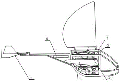
[0043] A flapping-wing coupled motion flapping-wing aircraft. Such asfigure 1 As shown, the flapping-wing aircraft is made up of a fuselage 1, a drive mechanism 3, two wings 4, an empennage mechanism 5 and a control system. Let the fuselage head be the front, the left side facing the fuselage head be the left, the front and rear directions be the vertical direction, and the left and right directions be the horizontal direction.

[0044] The fuselage 1 is formed by sequentially connecting the fuselage head 11 , the fuselage middle 10 and the fuselage tail 14 .

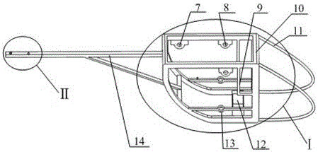
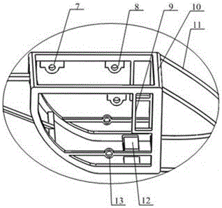
[0045] The structure of the middle part 10 of the fuselage is: the vertical frame on the left side and the vertical frame on the right side are connected into a box-shaped frame by four horizontal horizontal bars, and the vertical frames on both sides are arranged symmetrically. Longitudinal horizontal beams are arranged symmetrically near the bottom of the vertical frame, and first bearing blocks 13 are symmetrically ...

Embodiment 2

[0062] A flapping-wing coupled motion flapping-wing aircraft. Except following technical parameter, all the other are with embodiment 1:

[0063] The length of the lower horizontal bar in the longitudinal direction is 0.5 to 0.6 times that of the horizontal bar in the longitudinal direction, and the length of the rear vertical bar is 0.3 to 0.4 times that of the front vertical bar.

[0064] The fixed connection between the rear end of the longitudinal fixed rod and the middle of the longitudinal horizontal rod means that the angle between the longitudinal fixed rod and the longitudinal horizontal rod at the joint is 27-30°.

[0065] The width of the closed end of the concave member 34 is 0.7-0.8 times the width of the base of the airfoil 32 .

[0066] Compared with the prior art, this specific embodiment has the following positive effects:

[0067] This specific embodiment is made up of fuselage 1, driving mechanism 3, two wings 4, empennage mechanism 5 and control system, a...


PUM


Abstract

The invention relates to a flapping-torsion coupled motion flapping-wing aircraft. Its technical solution is: the flapping-wing aircraft is composed of a fuselage (1), a driving mechanism (3), two wings (4), an empennage mechanism (5) and a control system. The motor (22) transmits the motion to the first rotating shaft (25) through the gear, and the crank (26) installed at both ends of the first rotating shaft (25) drives the two wings (4) through two connecting rods (27) to realize the flapping motion. The small pulley (28) installed in the middle part of the first rotating shaft (25) is connected with the large pulley (31) by a belt, and the rotation of the large pulley (31) passes through the second connecting rod (17), the rocking bar (18) and two mechanisms. Wing (4) realizes the torsional motion of the wing. The transmitter (41) transmits the remote control signal to the receiver (6), controls the motor (22) to realize flapping and twisting of the wings, and controls the tail servo (38) to realize the steering of the aircraft. The invention has the characteristics of simple structure, less driving original moving parts, can realize flapping-torsion coupled flapping motion, flexible flight and large effective lift.

Description

technical field [0001] The invention belongs to the technical field of flapping-wing aircraft. In particular, it relates to a flapping-rotation coupled motion flapping-wing aircraft. Background technique [0002] Flapping wing flight has good maneuverability and flexibility. Compared with fixed-wing flight, at low Reynolds number, it can make full use of unsteady aerodynamic characteristics to obtain high lift, and has high flight stability. Compared with the single-degree-of-freedom flapping-wing movement, the multi-degree-of-freedom flapping-wing movement can better realize the attitude of flying creatures, the flight is flexible, and the flight mode can be better controlled during the movement. [0003] At present, most of the flapping-wing aircraft studied are single-degree-of-freedom mechanisms, and the realized operation form is simple. The flight flexibility and stability cannot be compared with flying creatures. The existing multi-degree-of-freedom flapping-wing ai...

Claims


Application Information

Patent Timeline
Patent Type & Authority Patents(China)
IPC IPC(8): B64C33/00B64C33/02
CPCB64C33/00B64C33/02B64U10/40B64U50/19
Inventor 侯宇阮龙欢童超段宇李诗雷
Owner WUHAN UNIV OF SCI & TECH
Why Eureka
Try Eureka