Matchstick head feeding equipment for matchstick production

A technology of match heads and matches, which is applied in matches and other directions, can solve the problems of low work efficiency, time-consuming and labor-intensive, etc.

Active Publication Date: 2020-11-17
刘丽文
View PDF5 Cites 1 Cited by
  • Summary
  • Abstract
  • Description
  • Claims
  • Application Information

AI Technical Summary

Problems solved by technology

[0005] In order to overcome the shortcomings of high degree of dependence on labor, low work efficiency, and time-consuming and labor-intensive work, the technical problem is t...

Method used


Image

  • Matchstick head feeding equipment for matchstick production
  • Matchstick head feeding equipment for matchstick production
  • Matchstick head feeding equipment for matchstick production

Examples


Embodiment 1

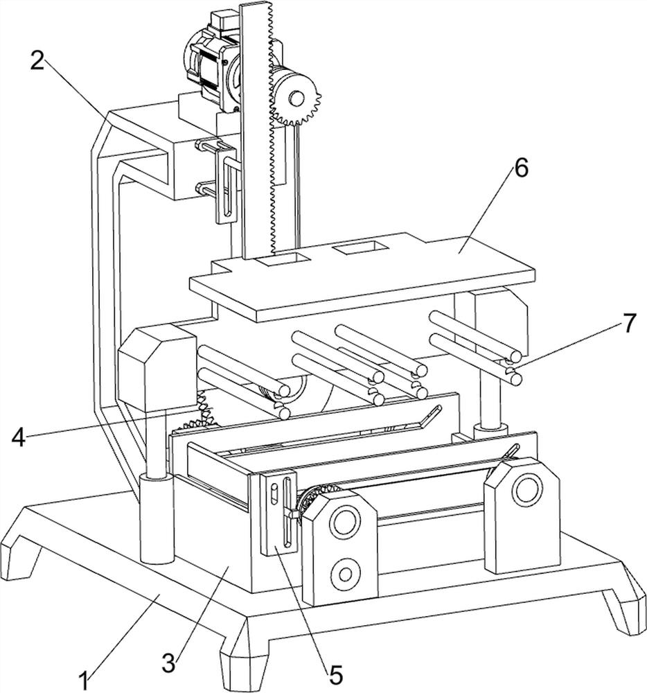
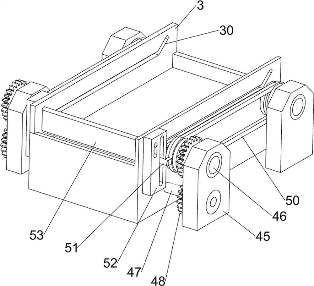
[0023] A matchhead feeding device for match production, such as Figure 1-5 As shown, it includes a base 1, a support frame 2, a discharge box 3, a drive mechanism 4 and a scraper mechanism 5, a support frame 2 is provided on the rear side of the base 1, a discharge box 3 is provided on the front side of the top of the base 1, and a discharge box 3 is provided on the front side of the top of the base 1. Case 3 front and back both sides tops all have guide hole 30, be provided with driving mechanism 4 between support frame 2 tops and base 1 top, discharge box 3 tops and base 1 tops are provided with scraper mechanism 5.

[0024] The staff first fills up the discharge box 3, fixes the match heads on the board, places the board with the match heads on the upper side of the discharge box 3, and then starts the driving mechanism 4 to work, and the driving mechanism 4 drives the scraping mechanism 5 work, and place the matchheads on the discharge box 3 for feeding, and the scraping ...

Embodiment 2

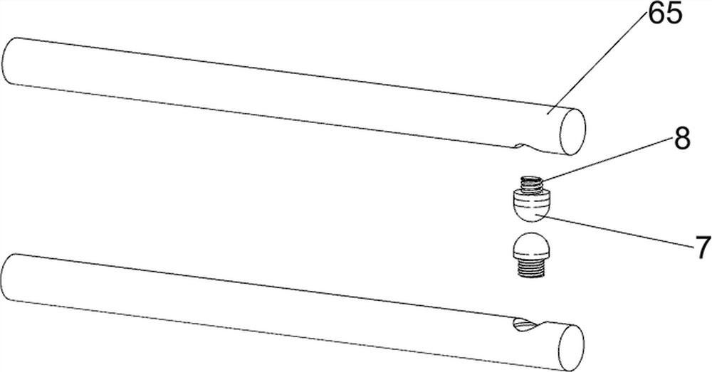
[0030] On the basis of Example 1, such as Figure 6-8As shown, it also includes a pressing mechanism 6, and the pressing mechanism 6 includes a sleeve 60, a first spring member 61, a compression rod 62, a first fixed block 63, a lower pressing plate 64, a support rod 65, a rack 66, a second Two missing gears 67, fixed rod 68, second fixed block 69 and guide block 610, base 1 top, left and right sides are all provided with sleeve 60, all sliding type is provided with compression rod 62 in the sleeve 60, compression rod 62 and sleeve A first spring member 61 is connected between the inner walls of the cylinder 60, a first fixing block 63 is provided on the top of the compression rod 62, a lower pressing plate 64 is arranged between the inner sides of the two first fixing blocks 63, and the rear side of the inner wall of the lower pressing plate 64 is up and down. Four sets of support rods 65 are arranged symmetrically, two support rods 65 form a group, a rack 66 is provided on t...


PUM


Abstract

The invention relates to feeding equipment, particularly to matchstick head feeding equipment for matchstick production, and provides matchstick head feeding equipment for matchstick production, wherein the equipment is high in mechanization degree, high in working efficiency, capable of saving time and labor and capable of integrating feeding and brushing. The matchstick head feeding equipment for matchstick production comprises: a base, wherein a supporting frame is arranged on one side of the base, a discharging box, wherein the top of the base is placed on one side of the discharging box,and guide holes are formed in the upper portions of the two sides of the discharging box, a driving mechanism arranged between the top of the supporting frame and the top of the base, and scraping mechanisms arranged at the upper portion of the discharging box and the top of the base. The matchstick head feeding equipment has the beneficial effects that a servo motor drives a material scraping plate to slide back and forth through a first missing gear and a gear set, so that materials in a discharging box are scraped to be flat and tidied.

Description

technical field [0001] The invention relates to a feeding device, in particular to a matchhead feeding device for match production. Background technique [0002] Match is based on the principle of heat generation by friction of objects, using the chemical activity of strong oxidizing agents and reducing agents to manufacture a kind of fire-making tool that can be ignited by friction. [0003] At present, most of the work of feeding match heads still relies on manpower to complete the production. The traditional process of feeding matches requires the cooperation of two people. One is responsible for scraping the surface of the material, and the other is responsible for feeding the match heads. Loading, the completion of the loading process depends on manual work, which is inefficient and time-consuming. [0004] How to design a match head feeding integrated machine with high degree of mechanization, high work efficiency, time saving and labor saving, brushing and feeding is...

Claims


Application Information

Patent Timeline
IPC IPC(8): C06F1/06C06F1/00
CPCC06F1/00C06F1/06
Inventor 刘丽文
Owner 刘丽文
Why Eureka
Try Eureka