Hoop type tool suspender device for changing steel pipe truss concrete arch bridge suspender

A steel tube truss and concrete technology, applied in truss bridges, bridge forms, erection/assembly of bridges, etc., can solve the problems of high construction cost, high manufacturing cost, not very practical, etc., achieve good social and economic benefits, low manufacturing cost, Wide range of effects

Active Publication Date: 2016-11-09
LIUZHOU OVM ENG
View PDF9 Cites 11 Cited by
  • Summary
  • Abstract
  • Description
  • Claims
  • Application Information

AI Technical Summary

Problems solved by technology

[0002] At present, most of the steel tube truss concrete arch bridge suspender replacement cable force conversion devices are mainly temporary suspenders or temporary hoisting devices, and the upper part of the arch needs to be fixed by welding to level the wedge or anti-slip stoppers to achieve the leveling of the arch and facilitate installation. The purpose of beam or anti-slip; its disadvantages are: high engineering work intensity, difficult to control the quality of on-site welding, easy to damage the arch rib and coating of the original steel pipe, wedge-shaped blocks cannot be used for turnover, the progress of demolition and restoration work is slow, and the construction cost is high
[0003] In order to solve the above problems, the patent number is 201520814605.4, the name of the invention is: "A traction tool hanger device for the replacement of the hanger of the steel pipe truss concrete arch bridge", the patent number is 201521046495.8, the name of the invention is: "A traction friction anchor Suspender replacement device" has disclosed two kinds of "arch bridge suspender replacement cable force conversion device", which solves the technical problems in the above-mentioned prior art, but there are many components involved in machining, and the manufacturing cost is relatively high. Especially the traction vault anchorage anti-skid system set on the vault has a large structure size, which is not practical in some places

Method used


Image

  • Hoop type tool suspender device for changing steel pipe truss concrete arch bridge suspender
  • Hoop type tool suspender device for changing steel pipe truss concrete arch bridge suspender
  • Hoop type tool suspender device for changing steel pipe truss concrete arch bridge suspender

Examples


Embodiment Construction

[0034] A hoop-type tool hanger device for replacing the hanger of a steel pipe truss concrete arch bridge

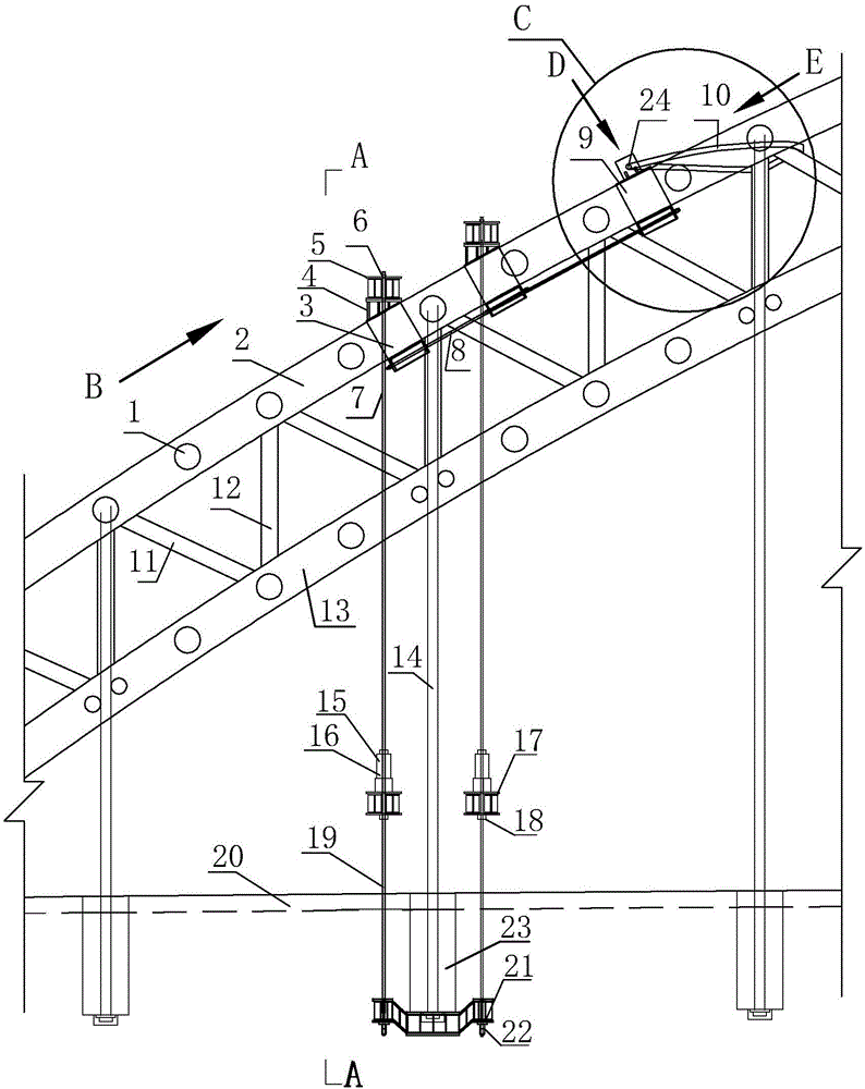
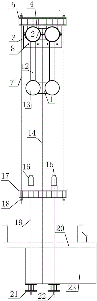
[0035] Such as figure 1 , figure 2 As shown, the hoop-type tool hanger device for replacing the hanger of the steel pipe truss concrete arch bridge includes: upper beam 5, tension end anchor I6, upper temporary cable 7, tension end anchor II15, conversion beam 17, Fixed end anchor I18, lower temporary cable 19, lower joist 21 and fixed end anchor II22;

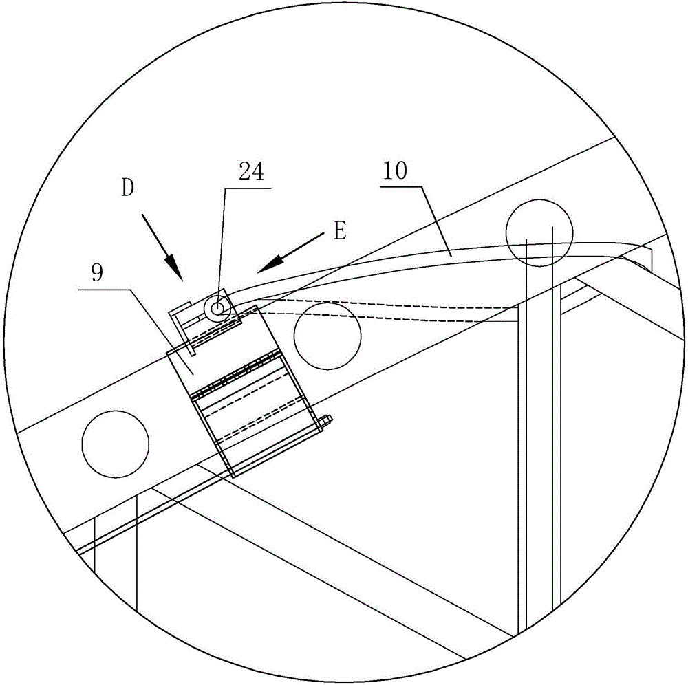
[0036] Such as figure 1 , figure 2 As shown, the hoop type tool hanger device also includes a hoop type vault anchorage anti-skid system installed on the arch of a steel pipe truss concrete arch bridge. Anchor hoop 9, leveling steel box 4, upper beam 5, anti-slip rope 8 and anti-slip hoop 3, one end of anchor hoop 9 is anchored on the steel pipe truss arch ring by winding through bolt 24 and sling 10, anti-slip One end of the slide cable 8 is fixedly connected to the bottom of the anchor hoop 9, and the other end ...


PUM


Abstract

The invention discloses a hoop type tool suspender device for changing a steel pipe truss concrete arch bridge suspender. The device comprises an upper cross beam, a tensioning-end anchorage, upper and lower temporary ropes, a conversion beam, a fixing-end anchorage, a lower joist and a hoop type arch crown anchoring antiskid system consisting of a bolt, a lifting belt, an anchoring hoop, a leveling steel box, an upper cross beam, an antiskid rope and an antiskid hoop, wherein one end of the anchoring hoop is anchored on a steel pipe truss arch ring by the bolt and the lifting belt through a winding way; one end of the antiskid rope is fixedly connected with the bottom of the anchoring hoop, and the other end is fixedly connected with the bottom of the antiskid hoop; and the antiskid hoop and the anchoring hoop are connected through a steel strand or a rigid pull rod. When the device is used for changing the suspender, with the hoop type anchoring antiskid system arranged on the arch, the upper temporary rope is connected with a bridge floor conversion beam, the lower joist is arranged below the lifting rod cross beam, the lower temporary rope is connected with the bridge floor conversion beam, and a jack on the bridge floor conversion beam is tensioned to realize conversion of the suspender force; and moreover, the structure is simple, and the manufacturing and construction cost is low.

Description

technical field [0001] The invention relates to a bridge construction machine tool, in particular to a tool suspender device for replacing the suspender of a steel tube truss concrete arch bridge. Background technique [0002] At present, most of the steel tube truss concrete arch bridge suspender replacement cable force conversion devices are mainly temporary suspenders or temporary hoisting devices, and the upper part of the arch needs to be fixed by welding to level the wedge or anti-slip stoppers to achieve the leveling of the arch and facilitate installation. The purpose of beam or anti-slip; its disadvantages are: high engineering work intensity, difficult to control the quality of on-site welding, easy to damage the arch rib and coating of the original steel pipe, the wedge block cannot be used for turnover, the progress of demolition and restoration work is slow, and the construction cost is high. [0003] In order to solve the above problems, the patent number is 20...

Claims


Application Information

Patent Timeline
Patent Type & Authority Applications(China)
IPC IPC(8): E01D21/00E01D19/14E01D6/02
CPCE01D6/02E01D19/14E01D21/00
Inventor 窦勇芝韦福堂莫迪基黎祖金肖朝辉粱黎霞罗迪
Owner LIUZHOU OVM ENG
Why Eureka
Try Eureka