Multifunctional guardrail for expressways, high-grade highways and common highways

A highway, high-level technology, applied in the directions of roads, roads, road safety devices, etc., can solve the problems of general stability and single function, and achieve the effect of reducing the difficulty of maintenance, ensuring the display effect, and facilitating the transportation and transfer of the guardrail.

Inactive Publication Date: 2020-11-17
江苏中路交通发展有限公司
0 Cites 3 Cited by

AI-Extracted Technical Summary

Problems solved by technology

[0003] Existing guardrails for highways, high-grade highways and ordinary highways have single functions and general...

Abstract

The invention discloses a multifunctional guardrail for expressways, high-grade highways and common highways. The multifunctional guardrail comprises two guardrail columns, a cross beam is welded between the two guardrail columns, wind power generation assemblies distributed at equal intervals are arranged between the two cross beam, reflective stripes are fixed to the outer walls of the two sidesof the two guardrail columns through bolts, supporting seats are welded to the bottom ends of the two guardrail columns, the bottom ends of the side walls of the two guardrail columns are sleeved with sliding sleeves, the same water tank is fixed to the side walls of the two sliding sleeves through bolts, spring pieces are clamped to the two sides of the top end of the water tank, and the top ends of the two spring pieces are clamped to the two ends of the outer wall of the bottom end of one cross beam correspondingly. According to the guardrail, information display is facilitated, the functions of the guardrail are enriched, the flexible transparent sleeve can be driven to rotate, dirt on the side wall of the flexible transparent sleeve can be removed in combination with the brush strips, the display effect can be guaranteed, daily cleaning and maintenance are facilitated, and the maintenance difficulty is reduced.

Application Domain

Cleaning using toolsRoadway safety arrangements

Technology Topic

Structural engineeringWater tanks +2

Image

  • Multifunctional guardrail for expressways, high-grade highways and common highways
  • Multifunctional guardrail for expressways, high-grade highways and common highways

Examples

  • Experimental program(1)

Example Embodiment

[0018] The following will clearly and completely describe the technical solutions in the embodiments of the present invention with reference to the accompanying drawings in the embodiments of the present invention. Obviously, the described embodiments are only some, not all, embodiments of the present invention.
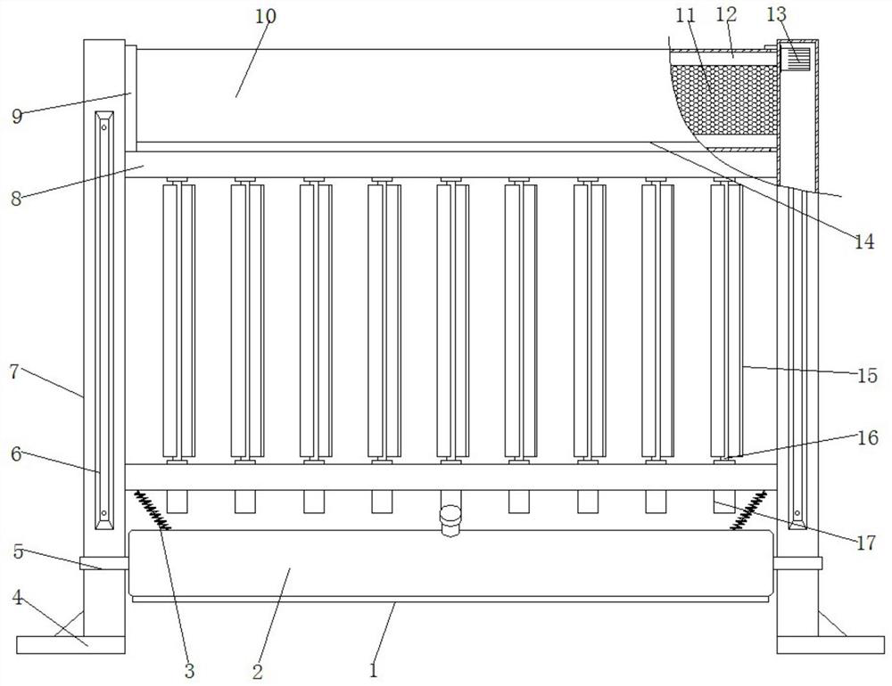
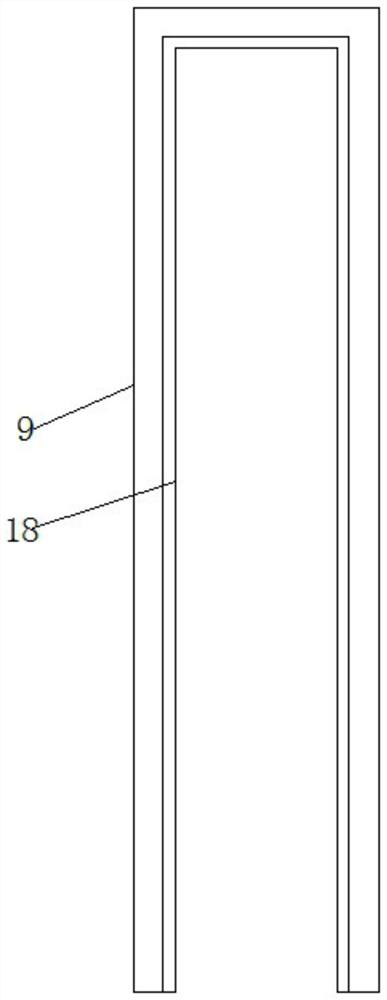
[0019] refer to Figure 1-2 , multifunctional guardrails for highways, high-grade highways and ordinary roads, including two guardrail columns 7, beams 8 welded between the two guardrail columns 7, and wind power generation components distributed equidistantly between the two beams 8, The outer walls on both sides of the two guardrail posts 7 are fixed with reflective strips 6 by bolts, the bottom ends of the two guardrail posts 7 are welded with support seats 4, and the bottom positions of the side walls of the two guardrail posts 7 are all provided with sliding sleeves 5. And the side walls of the two sliding sleeves 5 are fixed with the same water tank 2 by bolts, and spring parts 3 are clamped on both sides of the top of the water tank 2. Then, there are two supporting rollers 12 arranged in parallel at the top of the two guardrail posts 7, and the outer walls of the two supporting rollers 12 are covered with the same flexible transparent sleeve 10, and the flexible transparent sleeve 10 is arranged between the two guardrail posts 7. The brush bar 14 is fixed by bolts at the position 10, and the LED display screen 11 is fixed by bolts between the two guardrail columns 7, and the LED display screen 11 is located between the two support rollers 12, and the top of the inner wall of one of the guardrail columns 7 The position is fixed with a motor 13 by bolts, and the output shaft of the motor 13 is connected to one end of one of the support rollers 12. The wind power generation assembly includes a micro-generator 17, and the micro-generator 17 is fixed to the outer wall of the bottom end of one of the beams 8 by bolts. The input shaft of the generator 17 is fixed with a metal rod 16 by bolts, the top of the metal rod 16 is rotationally connected with the outer wall of the bottom end of another crossbeam 8, and the side wall of the metal rod 16 is welded with arc-shaped plates 15 equidistant and circularly distributed. U-shaped covers 9 are welded on both sides of the wall close to the flexible transparent cover 10, and the two ends of the flexible transparent cover 10 are respectively sleeved in two U-shaped covers 9, and the inner walls of the two U-shaped covers 9 are provided with sealing grooves , and a sealing strip 18 is clamped on the inner wall of the sealing groove.
[0020] In the present invention, the outer wall of the bottom end of the water tank 2 is bonded with a non-slip mat 1, and the outer wall of the bottom end of the anti-slip mat 1 is provided with anti-slip lines, and the top and bottom positions of the side walls of the water tank 2 are respectively provided with a liquid inlet pipe and a liquid outlet pipe, and Both the liquid inlet pipe and the liquid outlet pipe are clamped with blocks, the motor 13 is connected with a switch, and the switch is connected with a microprocessor, and the LED display 11 is connected with the microprocessor through a signal line, and the microprocessor model is 79RC32H434-266BC.
[0021] Working principle: When in use, put the guardrail in a suitable position, then fill the water tank 2 with water, and the water tank 2 will move down under the action of the weight of the water body, so that the water tank 2 is in contact with the ground to improve the stability of the guardrail. When the car passes the guardrail , to drive the gas flow, cooperate with the set arc plate 15, drive the metal rod 16 to rotate, realize the power generation of the micro generator 17, the LED display screen 11 is convenient for displaying information, enrich the function of the guardrail, and cooperate with the set motor 13 and support roller 12 at the same time, It can drive the flexible transparent cover 10 to rotate, combined with the provided brush bar 14, it can clean the dirt on the side wall of the flexible transparent cover 10, which can ensure the display effect, facilitate daily cleaning and maintenance, and reduce the difficulty of maintenance.
[0022] The above is only a preferred embodiment of the present invention, but the scope of protection of the present invention is not limited thereto, any person familiar with the technical field within the technical scope disclosed in the present invention, according to the technical solution of the present invention Any equivalent replacement or change of the inventive concept thereof shall fall within the protection scope of the present invention.

PUM

no PUM

Description & Claims & Application Information

We can also present the details of the Description, Claims and Application information to help users get a comprehensive understanding of the technical details of the patent, such as background art, summary of invention, brief description of drawings, description of embodiments, and other original content. On the other hand, users can also determine the specific scope of protection of the technology through the list of claims; as well as understand the changes in the life cycle of the technology with the presentation of the patent timeline. Login to view more.

Similar technology patents

Backlight module with anti-light-leakage function

PendingCN109375418AGuaranteed display effectincrease contact area
Owner:BENGBU GUOXIAN TECH CO LTD

Display substrate, manufacturing method thereof and display device

PendingCN114361220Aavoid influenceGuaranteed display effect
Owner:BOE TECH GRP CO LTD +1

Market research service network locator

InactiveCN108073226APowerfulEasy to display information
Owner:天津仰先科技发展有限公司

Display screen eye protection lamp

PendingCN114151746AGuaranteed display effectavoid dizziness
Owner:SHANGHAI TOPMB LIGHTING TECH CO LTD

A display method and handheld electronic device

ActiveCN108604367Bclear imageGuaranteed display effect
Owner:HUAWEI TECH CO LTD

Method and device for displaying image and equipment

InactiveCN107273015AGuaranteed display effect
Owner:BAIDU ONLINE NETWORK TECH (BEIJIBG) CO LTD

Classification and recommendation of technical efficacy words

  • Guaranteed display effect
  • Easy to display information

Pulling type flexible screen

ActiveCN110428732AGuaranteed display effectConvenience guaranteed
Owner:SHENZHEN BIOSLED TECH

Flexible display module and display device

InactiveCN110428735AImprove resilienceGuaranteed display effect
Owner:WUHAN TIANMA MICRO ELECTRONICS CO LTD

Array substrate, manufacture method thereof, and display device

InactiveCN104934443AOptimize connectionGuaranteed display effect
Owner:BOE TECH GRP CO LTD +1

Display device

PendingCN112382200Akeep it flatGuaranteed display effect
Owner:BOE TECH GRP CO LTD

Display panel, manufacturing method of display panel and display device

ActiveCN109326225Asmall sizeGuaranteed display effect
Owner:WUHAN TIANMA MICRO ELECTRONICS CO LTD

Market research service network locator

InactiveCN108073226APowerfulEasy to display information
Owner:天津仰先科技发展有限公司
Why Eureka
Try Eureka