Hydroelectric turbine generator component

A technology for hydroelectric turbines and generators, applied in the directions of hydroelectric power generation, engine components, machines/engines, etc., can solve the problems of reducing the diversion speed of high-pressure water flow, reducing the adaptability of subsequent devices, and not being able to limit the flow of water at high altitudes. The effect of adapting performance, preventing leakage, and facilitating regulation

Inactive Publication Date: 2020-11-17
王照雨
View PDF0 Cites 1 Cited by
  • Summary
  • Abstract
  • Description
  • Claims
  • Application Information

AI Technical Summary

Problems solved by technology

[0003] Most of the turbine water flow baffles of the existing hydroelectric turbine generators are limited outside the turbine to block the water flow, but in this way, the high pressure water flow is reduced because the baffle body has a certain volume and width. The diversion speed when passing through the inside of the shell reduces the speed of the turbine driven by the water flow and reduces the efficiency of subsequent power generation, and the existing diversion mechanism cannot quickly and stably limit the flow of high water flow , which reduces the adaptability of subsequent devices, it is necessary to propose a hydroelectric turbine generator component

Method used


Image

  • Hydroelectric turbine generator component
  • Hydroelectric turbine generator component
  • Hydroelectric turbine generator component

Examples


Embodiment Construction

[0034] In order to make the technical means, creative features, goals and effects achieved by the present invention easy to understand, the present invention will be further described below in conjunction with specific embodiments.

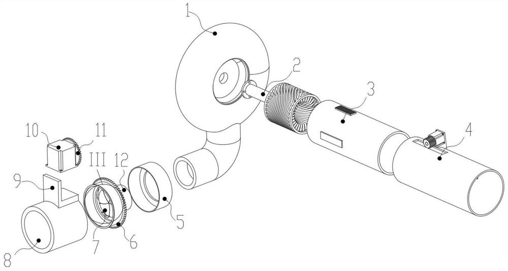
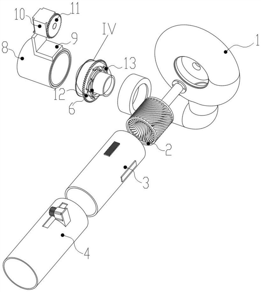
[0035] Such as Figure 1-Figure 11 As shown, a hydroelectric turbine generator component according to the present invention includes a support mechanism 1, a flow guide mechanism 2, a current limiting mechanism 3 and an adjustment mechanism 4,

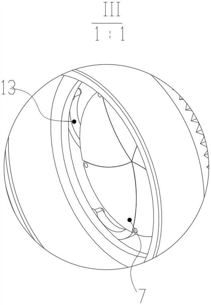
[0036]The inner end surface of the support mechanism 1 is rotatably connected with the guide mechanism 2, and the inner end surface of the support mechanism 1 is fixedly connected with the adjustment mechanism 4 for support. The mechanism 3 and the support mechanism 1 are slidingly plugged in, the side end surface of the support mechanism 1 is sealed and rotated with a seal cover 5, and the inner end surface of the seal cover 5 is sealed and rotated with a positioning installation tube 12, and the bottom e...


PUM


Abstract

The invention relates to the field of turbine power generation devices, in particular to a hydroelectric turbine generator component. The hydroelectric turbine generator component comprises a supporting mechanism, a flow guiding mechanism, a flow limiting mechanism and an adjusting mechanism, wherein the flow guiding mechanism is rotationally clamped to the inner end surface of the supporting mechanism, the adjusting mechanism for supporting is fixedly connected to the inner end surface of the supporting mechanism, the flow limiting mechanism is slidably clamped to the inner end surface of theadjusting mechanism, and the flow limiting mechanism is slidably inserted into the supporting mechanism. The hydroelectric turbine generator component has the beneficial effects that through the flowlimiting mechanism and the adjusting mechanism, a user can conveniently adjust the speed of water flow by adjusting the displacement distance between the flow limiting mechanism and the adjusting mechanism, so that the subsequent power generation is conveniently carried out according to requirements; and meanwhile, when the flow limiting mechanism displaces to the limit, no barrier exists in an installation groove, so that the speed of the water flow is improved to the maximum extent, and thus the power generation efficiency is improved.

Description

technical field [0001] The invention relates to the field of turbine power generation equipment, in particular to a hydroelectric turbine generator component. Background technique [0002] The principle of the hydroelectric turbine generator is: the water flow impacts the turbine assembly to make it rotate, and drives the rotor of the generator to rotate through the main shaft, and direct current is passed into the rotor coil of the generator, and the rotor coil will generate a rotating magnetic field, and the magnetic field lines are in the process of rotation According to the principle of electromagnetic induction, a voltage will be generated in the stator coil, and after the stator coil is connected to the load, a current will be generated in the stator coil. [0003] Most of the turbine water flow baffles of the existing hydroelectric turbine generators are limited outside the turbine to block the water flow, but in this way, the high pressure water flow is reduced becau...

Claims


Application Information

Patent Timeline
Patent Type & Authority Applications(China)
IPC IPC(8): F03B13/00F03B11/00F03B15/06F03B3/12F03B3/18
CPCF03B3/12F03B3/18F03B11/00F03B11/006F03B13/00F03B15/06F05B2220/706Y02E10/20
Inventor 王照雨李浩
Owner 王照雨
Why Eureka
Try Eureka