Building verticality measuring device

A measuring device and verticality technology, applied in the directions of measuring devices, measuring instruments, surveying and navigation, etc., can solve the problems of time-consuming and energy-consuming, inaccurate floor data collection, lack of ability to adapt to rough and potholes, etc. The effect of precision

Active Publication Date: 2020-11-17
上海博骜建筑工程设计有限公司
6 Cites 0 Cited by

AI-Extracted Technical Summary

Problems solved by technology

[0004] In order to overcome the shortcomings of existing verticality detection instruments that do not have the ability to adapt to rough and potholed ground, consume time and energy, and lead to inaccurate floor data collect...

Abstract

The invention relates to a measuring device, in particular to a building perpendicularity measuring device. The building perpendicularity measuring device can accurately detect the floor perpendicularity and improve the quality of later decoration construction. According to the technical scheme, the building perpendicularity measuring device comprises: a horizontal plate and a connecting disc, wherein the top of the horizontal plate is connected with the connecting disc; guide sleeves which are connected to the two sides of the horizontal plate; a drilling mechanism, wherein the top of the guide sleeve is connected with the drilling mechanism; a measuring mechanism, wherein the top of the connecting disc is connected with the measuring mechanism. Through the drilling mechanism, the measuring mechanism and the lifting mechanism, the ground can be drilled, then the measuring mechanism is lifted, the measuring mechanism measures the ground, and therefore the measuring accuracy of people can be improved.

Application Domain

Surveying instruments

Technology Topic

Floor levelMeasurement device +5

Image

  • Building verticality measuring device
  • Building verticality measuring device
  • Building verticality measuring device

Examples

  • Experimental program(3)
  • Effect test(1)

Example Embodiment

[0050] Example 1
[0051] A measuring device for verticality of buildings, such as figure 1 As shown, it includes a horizontal plate 1, a connecting plate 2, a guide sleeve 3, a drilling mechanism 4, and a measuring mechanism 5. The top of the horizontal plate 1 is connected with a connecting plate 2 in the middle, and the left and right sides of the horizontal plate 1 are connected with guide sleeves 3. A drilling mechanism 4 is connected to the top of the guide sleeve 3, and a measuring mechanism 5 is connected to the top of the connecting plate 2.
[0052] When people need to detect whether the building floor is vertical, they first adjust the height of the parts of the drilling mechanism 4 according to the thickness of the floor, and then make the parts of the drilling mechanism 4 fit the bottom surface, and then start the parts of the drilling mechanism 4. Make the parts of the drilling mechanism 4 drill holes on the bottom surface. The parts of the drilling mechanism 4, the measuring mechanism 5, the horizontal plate 1 and the connecting plate 2 move downwards with the drilling, when the horizontal plate 1 side is attached to the bottom surface When people close the drilling mechanism 4, then people move the parts of the measuring mechanism 5 upward for a certain distance, and loosen the parts of the drilling mechanism 4. With the cooperation of the measuring mechanism 5, it can be detected whether the building is vertical. , People can take out the device.

Example Embodiment

[0053] Example 2
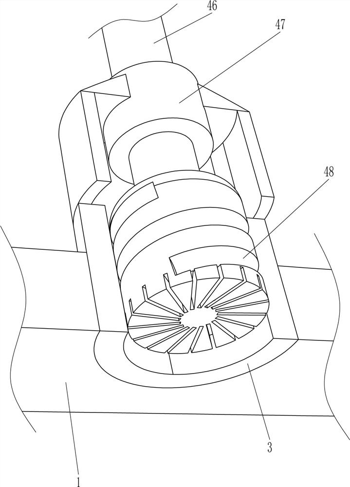
[0054] On the basis of Example 1, such as Figure 1-3 As shown, the drilling mechanism 4 includes a guide rod 41, a damping sleeve 42, an arc-shaped rod 43, a fixed ring 44, a drive motor 45, a transmission shaft 46, an anti-deflection sleeve 47 and a flat-bottom drill bit 48. The horizontal plate 1 is connected to the middle of the rear side There is a guide rod 41. A damping sleeve 42 is slidably connected to the guide rod 41. Both the left and right sides of the front of the damping sleeve 42 are connected with arc-shaped rods 43. The arc-shaped rods 43 are connected with a drive motor 45. An anti-deflection sleeve 47 is connected. The output shaft of the drive motor 45 is connected with a transmission shaft 46. The lower side of the transmission shaft 46 passes through the anti-deflection sleeve 47 and the guide sleeve 3. The bottom of the transmission shaft 46 is connected with a flat-bottomed drill 48. 48 through the guide sleeve 3.
[0055] When people need to detect whether the building floor is vertical, they first hold the device, and then move the damping sleeve 42, the arc-shaped rod 43, the drive motor 45, the fixed ring 44, the transmission shaft 46, and the flat-bottom drill bit 48 downward to make the flat bottom The drill bit 48 contacts the bottom surface, and then people start the drive motor 45. The output shaft of the drive motor 45 rotates to drive the transmission shaft 46 and the flat bottom drill bit 48 to continuously rotate, so that the flat bottom drill bit 48 punches the bottom surface. The motor 45, the fixed ring 44, and the transmission shaft 46 move downwards with the flat-bottom drill 48 punching holes. After the flat-bottom drill 48 punches the holes, people can move the measuring mechanism 5 close to the ground. With the cooperation of the measuring mechanism 5, it can detect After checking whether the building is vertical, people move the damping sleeve 42, the arc-shaped rod 43, the drive motor 45, the fixed ring 44, the transmission shaft 46, and the flat-bottom drill bit 48 upward to reset.
[0056] The measuring mechanism 5 includes a column 51, a mounting plate 52 and a verticality detector 53. A column 51 is connected to the top of the connecting plate 2, a mounting plate 52 is connected to the top of the column 51, and a verticality detector 53 is connected to the top of the mounting plate 52.
[0057] When the holes are drilled, people move the column 51, the mounting plate 52 and the verticality detector 53 down close to the ground. When the distance between the mounting plate 52 and the ground is a little different, stop moving, and the verticality detector 53 can detect Whether the building is vertical.

Example Embodiment

[0058] Example 3
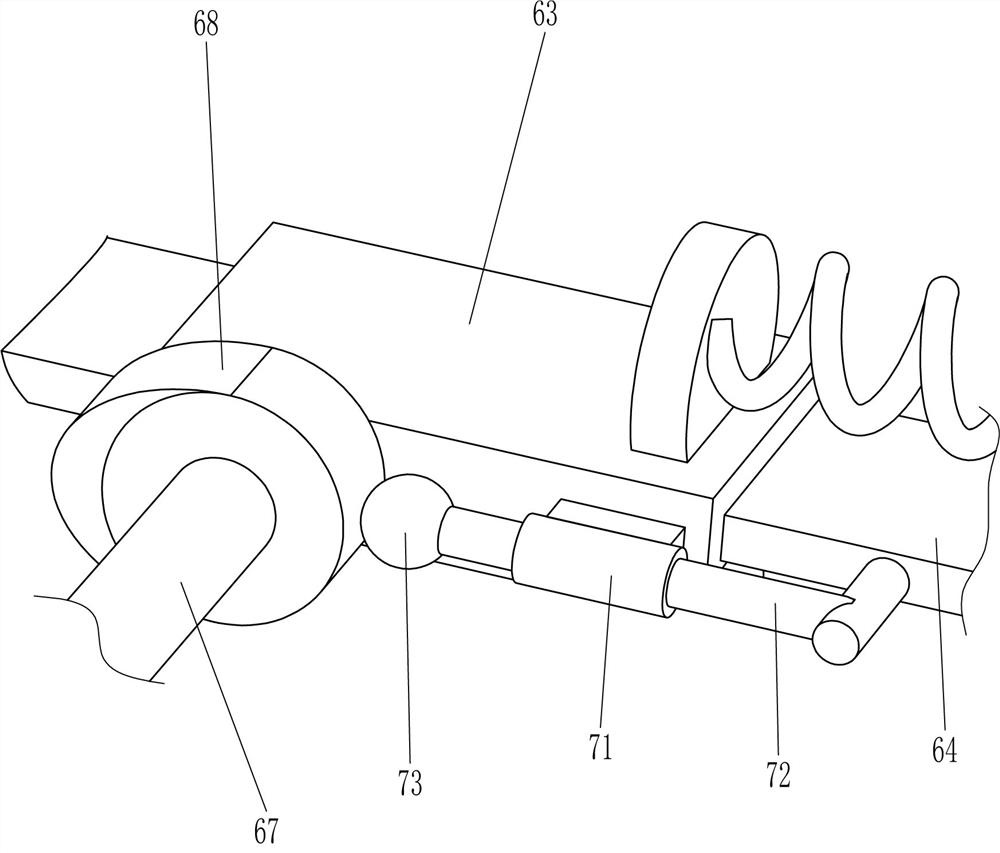
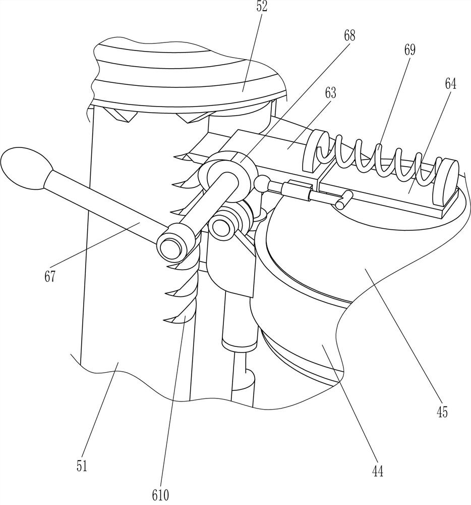
[0059] On the basis of Example 2, such as Figure 4-6 As shown, it also includes a lifting mechanism 6. The lifting mechanism 6 includes a guide tube 61, a sliding rod 62, a square hole sleeve 63, a guide plate 64, a support seat 65, a contact wheel 66, a rotating rod 67, a cam 68, and a second spring 69. The fixing ring 44 on the right side is connected with a guide tube 61 on the left side, a sliding rod 62 is slidably connected in the guide tube 61, a square hole sleeve 63 is connected to the top of the sliding rod 62, and a guide plate is slidably connected in the square hole sleeve 63 64. A second spring 69 is connected between the top right side of the guide plate 64 and the top right side of the square hole sleeve 63. The right side of the column 51 is evenly provided with a card slot 610, and the card slot 610 is clamped and fixed to the left side of the guide plate 64 A support base 65 is connected to the front of the left part of the ring 44. The upper part of the support base 65 is rotatably connected to a contact wheel 66. The front left part of the square hole sleeve 63 is rotatably connected to a rotating rod 67. The rear of the rotating rod 67 is connected to a cam 68. The cam 68 is press-fitted with the contact wheel 66.

PUM

no PUM

Description & Claims & Application Information

We can also present the details of the Description, Claims and Application information to help users get a comprehensive understanding of the technical details of the patent, such as background art, summary of invention, brief description of drawings, description of embodiments, and other original content. On the other hand, users can also determine the specific scope of protection of the technology through the list of claims; as well as understand the changes in the life cycle of the technology with the presentation of the patent timeline. Login to view more.

Similar technology patents

Measurement method of thickness of subsurface damaged layer of bucky optical material

InactiveCN101672625AHigh precisionStrong engineering applicability
Owner:XI AN JIAOTONG UNIV

Classification and recommendation of technical efficacy words

  • High precision

Method for forecasting short-term power in wind power station

InactiveCN102102626AHigh precision
Owner:NORTH CHINA ELECTRIC POWER UNIV (BAODING) +1

Numerical control machine tool wear monitoring method

InactiveCN102091972AHigh precisionReal-time monitoring of tool wear
Owner:HUAZHONG UNIV OF SCI & TECH +1

Advertisement recommendation method and apparatus

ActiveCN104965890AHigh precisionPrecise screening
Owner:SHENZHEN TENCENT COMP SYST CO LTD
Why Eureka
Try Eureka