
Device related to resers

A technology of risers and components, applied in the field of risers, can solve the problems of small flexibility and complexity of movement

Inactive Publication Date: 2003-08-27
STATOIL ASA PETRO SA (NO)
View PDF3 Cites 0 Cited by
  • Summary
  • Abstract
  • Description
  • Claims
  • Application Information

AI Technical Summary

Problems solved by technology

[0007] The disadvantage of the above US patent is that it has little flexibility relative to the large movements on the riser
and it requires a relatively complicated operation to connect the anchor to the riser on the seabed

Method used


Image

  • Device related to resers
  • Device related to resers
  • Device related to resers

Examples


Embodiment Construction

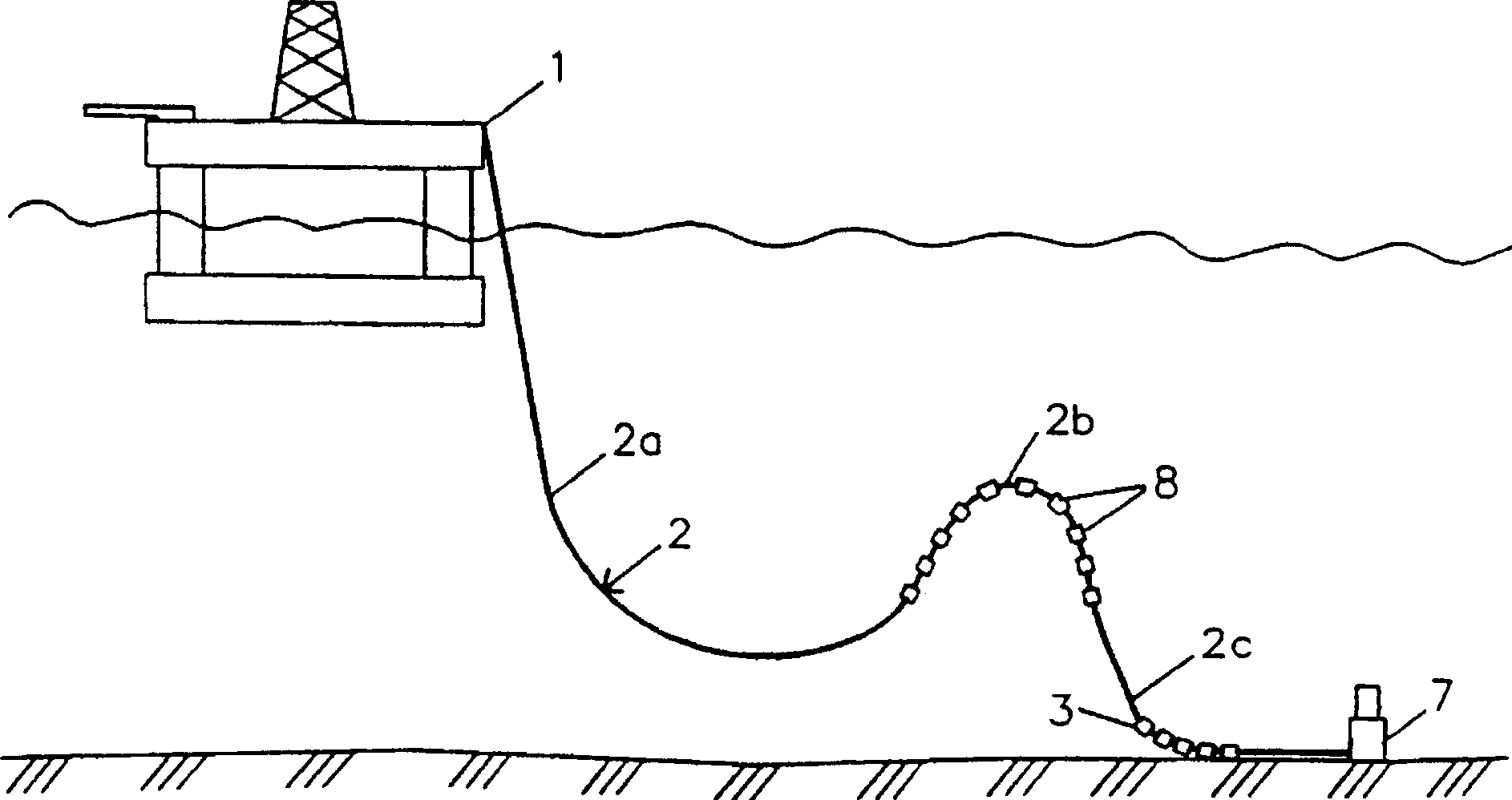
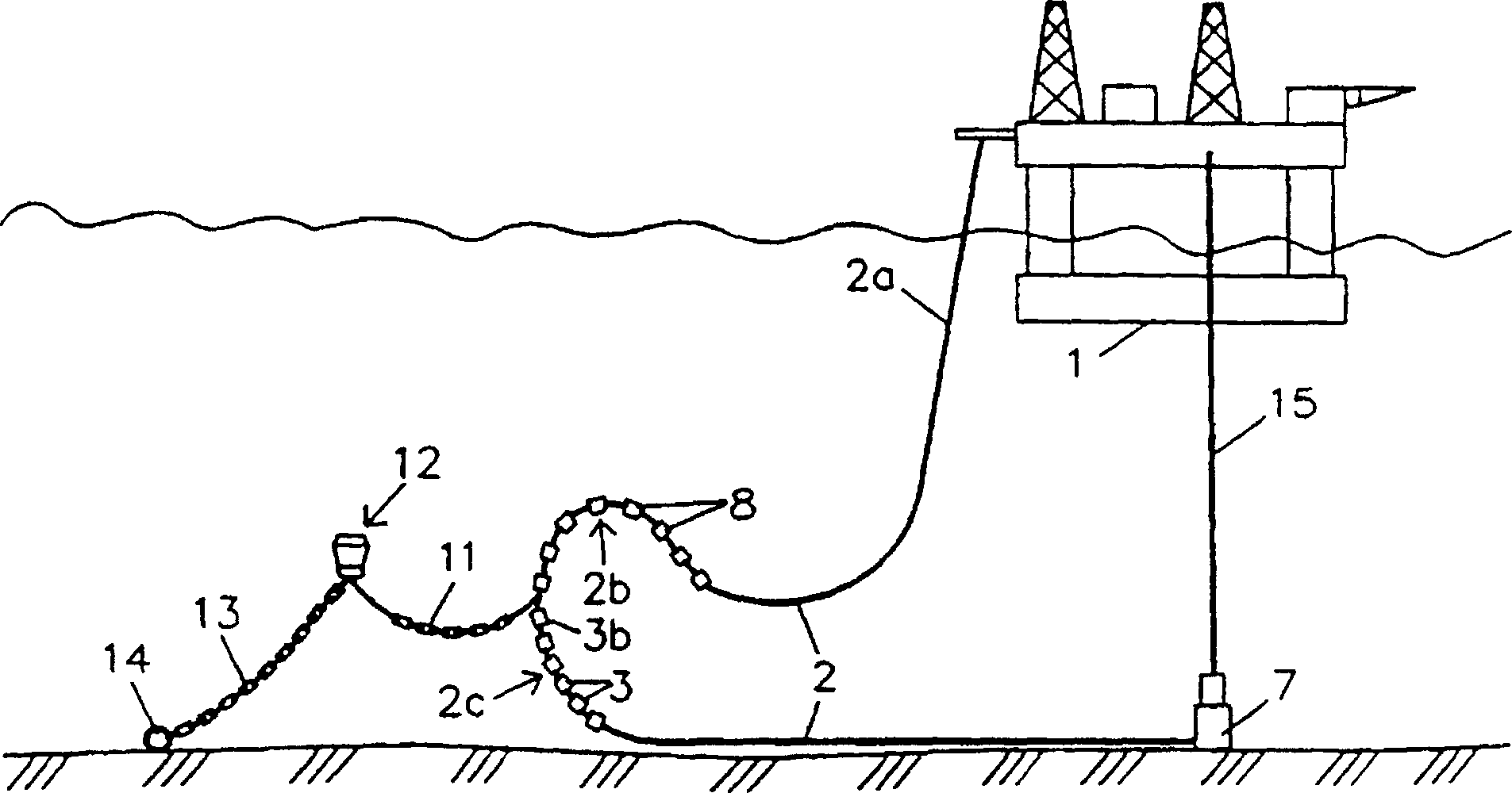
[0019] Figure 1a , a floating platform 1 is shown. A riser 2 is connected to the platform by means of a coupling mounted to a mounting deck. The platform itself is not essential to the invention, but the upper part of the riser may of course be coupled to other components, such as a vessel, in particular a submersible turret loading vessel or extraction vessel.

[0020] In the figure, the upper part 2a of the riser hangs substantially vertically. The middle part 2b has, in a known manner, a number of buoyancy elements 8 provided on the middle part for bending the riser on this part.

[0021] The riser also includes a lower portion 2c below the buoyancy elements. The lower part 2c extends at least down to the sea bottom, preferably along the sea bottom. A number of counterweight elements 3 are arranged on the lower part in order to balance the buoyancy forces generated by the buoyancy elements, which at the same time act to limit the vertical movement of the riser. Prefera...


PUM


Abstract

Device related to risers(2), especially for transferring fluids between a construction(7)by the sea floor and a second construction at or close to the surface, comprising: an upper essentially vertically extending part(2a)connected in its upper end to the construction at the sea surface; an intermediate part(2b)of the riser(2)connected to one or more buoyancy elements along at least a part of its length; and a lower part(2c)having a lower end connected to the construction(1)at the sea floor, one or more weight elements(3)being provided at the lower part(2c)of the riser(2).

Description

technical field [0001] The invention relates to a riser for conveying liquid between a first member on the seabed and a second member on the sea surface, comprising an upper portion extending approximately vertically and connected at its upper end to the surface member, a An intermediate portion of the riser connecting at least a portion of one or more buoyancy elements, and a lower portion the lower end of which is connected to the subsea structure. Background technique [0002] Many different types of risers are known for conveying liquids from the seabed to the surface. Common configurations are types such as "Lazy S" and "Steep S", both of which have risers extending to the seafloor through an intermediate region. In the middle portion, the riser is connected to one or more buoyancy elements which lift the corresponding portion of the riser and form a downwardly concave curved surface. [0003] From the above intermediate region, in the "Lazy S" configuration, the rise...

Claims


Application Information

Patent Timeline
IPC IPC(8): E21B17/01E21B43/01
CPCE21B43/01E21B17/015
Inventor 克努特·哈里·菲耶尔
Owner STATOIL ASA PETRO SA (NO)
Learn More