
Hydraulic adjusting device and plunger piston

A technology of hydraulic adjustment device and plunger, which is applied in the direction of valve device, engine components, machine/engine, etc., which can solve the problems of increasing the manufacturing cost of parts, and achieve the effect of facilitating discharge, reducing processing cost and concentrating gas

Inactive Publication Date: 2019-06-21
SCHAEFFLER TECH AG & CO KG
View PDF0 Cites 0 Cited by
  • Summary
  • Abstract
  • Description
  • Claims
  • Application Information

AI Technical Summary

Problems solved by technology

[0004] However, the oil leakage drop time between the plunger and the housing is mainly controlled by the dimensional parameters and roundness of the outer wall of the plunger and the inner wall of the housing, and the precision machining between the housing and the plunger will increase the manufacturing of the entire part cost

Method used


Image

  • Hydraulic adjusting device and plunger piston
  • Hydraulic adjusting device and plunger piston
  • Hydraulic adjusting device and plunger piston

Examples


Embodiment Construction

[0046] It can be seen from the background art that the gap between the plunger and the housing of the hydraulic adjustment device is related to the accuracy of the oil leakage control time, which leads to high processing cost of the plunger.

[0047] Now combine a hydraulic gap adjuster to analyze the reason.

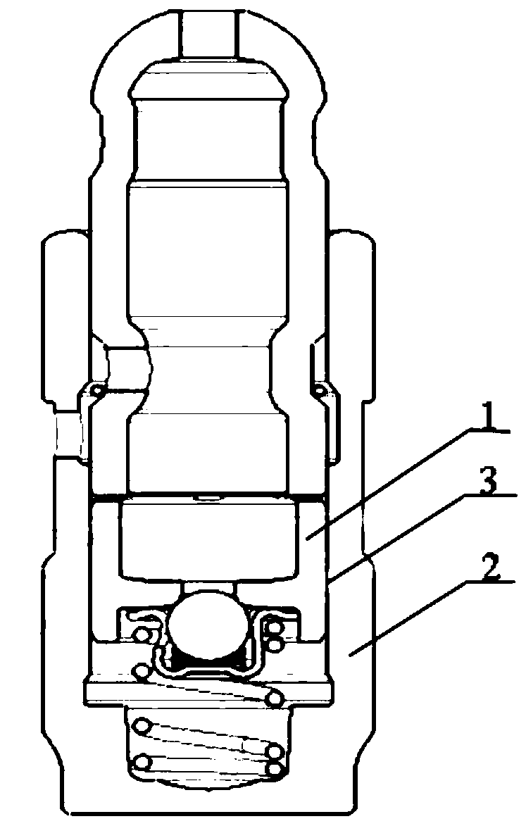
[0048] Please refer to figure 1 , figure 1 It is a sectional view of a gap adjuster.

[0049] like figure 1 As shown, there is a gap 3 between the housing 2 and the plunger 1 of the clearance adjuster, so that the leakage oil in the high pressure chamber leaks out along the gap 3, however, due to the gap 3 between the housing 2 and the plunger 1 determines Therefore, the machining accuracy of the contact area between housing 2 and plunger 1 is high. Moreover, due to the different oil leakage descending time required by customers, it is necessary to select and match the plunger and housing in groups, which is time-consuming. exhausting.

[0050] In order to solve th...


PUM


Abstract

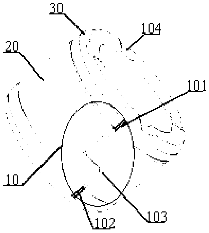
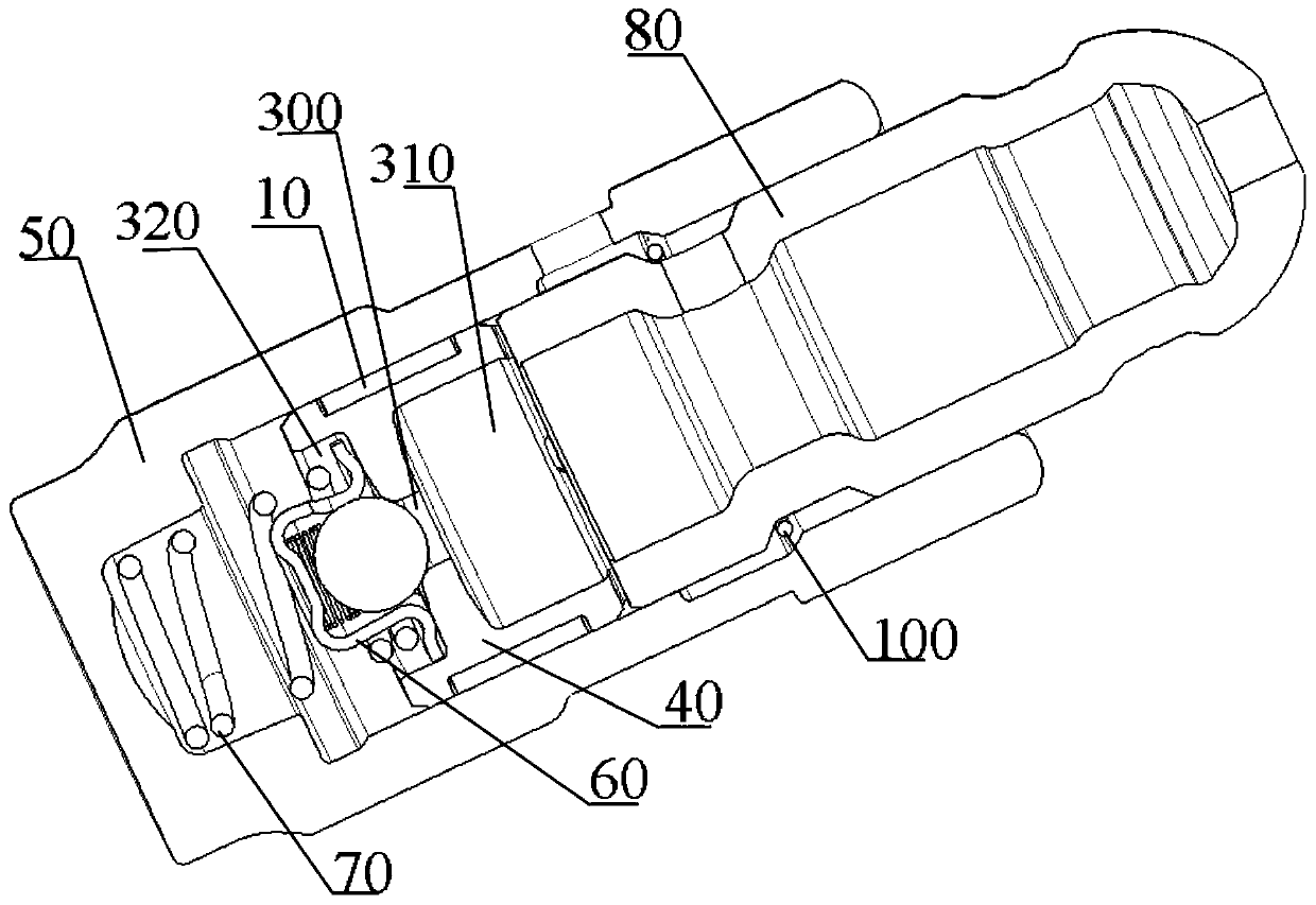
The invention relates to a hydraulic adjusting device and a plunger piston. The plunger piston is axially provided with a through hole; the outer ring surface of the plunger piston is provided with anoil drainage groove, the oil drainage groove extends from one axial end to the other axial end of the plunger piston, and the outer ring surface of the plunger piston is in interference fit with theinner wall of a shell of the hydraulic adjusting device, so as to prevent liquid in the high-pressure cavity of the hydraulic adjusting device from leaking along a gap between the plunger piston and acavity of the shell. The oil drainage groove extending from one axial end to the other axial end of the plunger piston is formed in the outer ring surface of the plunger piston, so that the hydraulicoil in the high-pressure cavity can flow out along the oil drainage groove after the interference fit is formed between the plunger piston and the cavity of the shell, the falling time of the oil drainage can be controlled by changing the shape of the oil drainage groove, and the machining cost of the plunger piston is reduced.

Description

technical field [0001] The embodiments of the present invention relate to the field of hydraulic technology, and in particular to a hydraulic adjustment device and a plunger. Background technique [0002] Hydraulic lash adjusters (sometimes referred to as "tappets") for internal combustion engines have been used for many years to eliminate the gap or gap between engine valve train components under changing operating conditions, thereby maintaining efficiency and reducing valve train noise and wear. [0003] Leakage Falling Time (LDT) is the core parameter of hydraulic lash adjusters. This time is a quantity used to express the magnitude of the rate at which oil is drained through the leakage gap between the plunger and the housing. There is usually a certain gap between the plunger and the inner wall of the housing so as to achieve a certain settlement value, and the settlement value corresponds to a certain settlement time. According to the different needs of users, the ...

Claims


Application Information

Patent Timeline
Patent Type & Authority Applications(China)
IPC IPC(8): F01L1/245
Inventor 刘浩阳荣
Owner SCHAEFFLER TECH AG & CO KG
Learn More