Circuit board, light-emitting panel and display deviceli

A light-emitting panel and circuit board technology, which is applied in the direction of circuits, electrical components, and electric solid-state devices, can solve the problems of light-emitting elements that are easy to fall off, optical utilization, inability to accurately control the position of the patch, and light-emitting elements that are easy to shift and tilt. To achieve the effect of preventing deviation or tilting, ensuring stability and ensuring performance requirements

Active Publication Date: 2020-11-17
SHANGHAI TIANMA MICRO ELECTRONICS CO LTD
View PDF7 Cites 1 Cited by
  • Summary
  • Abstract
  • Description
  • Claims
  • Application Information

AI Technical Summary

Problems solved by technology

Due to defects in the structural design of the existing circuit boards, the position of the light-emitting element cannot be accurately controlled during the placement process, and the light-emitting element is easy to shift and tilt, resulting in the light-emitting element being easy to fall off and reducing the optical utilization rate.

Method used


Image

  • Circuit board, light-emitting panel and display deviceli
  • Circuit board, light-emitting panel and display deviceli
  • Circuit board, light-emitting panel and display deviceli

Examples


Embodiment Construction

[0037] The characteristics and exemplary embodiments of various aspects of the present invention will be described in detail below. In order to make the purpose, technical solutions and advantages of the present invention clearer, the present invention will be further described in detail below in conjunction with the accompanying drawings and specific embodiments. It should be understood that the specific embodiments described here are only configured to explain the present invention, not to limit the present invention. It will be apparent to one skilled in the art that the present invention may be practiced without some of these specific details. The following description of the embodiments is only to provide a better understanding of the present invention by showing examples of the present invention.

[0038] It should be noted that in this article, relational terms such as first and second are only used to distinguish one entity or operation from another entity or operation...


PUM


Abstract

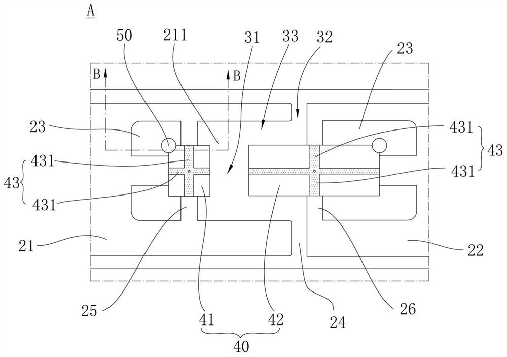
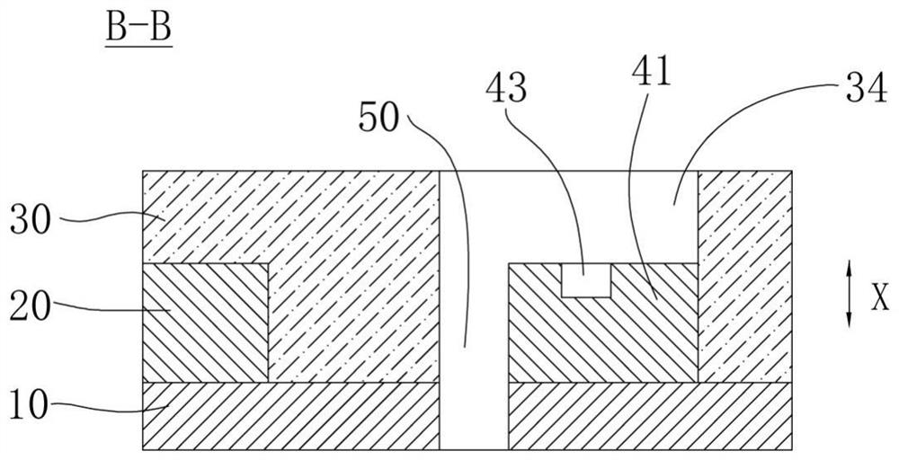
The invention relates to a circuit board, a light-emitting panel and a display device. The circuit board comprises a base material, a metal wiring layer, an insulating layer and a bonding pad unit. The metal wiring layer is arranged on the base material and comprises first metal wires and second metal wires, and the first metal wires and the second metal wires are distributed at intervals throughthe first openings. The insulating layer covers the metal wiring layer and the substrate exposed by the first opening. The bonding pad units are distributed in an array mode and exposed out of the insulating layer, each bonding pad unit comprises a first bonding pad and a second bonding pad which are arranged in pairs, the first bonding pads are connected with the first metal wires, the second bonding pads are connected with the second metal wires, and backflow grooves are formed in the bonding pad units. The embodiment of the invention can be used for controlling the light-emitting element, the light-emitting element is easy to position during surface mounting, the light-emitting element can be effectively prevented from inclining, the stability of connection between the light-emitting element and the circuit board is ensured, and the optical utilization rate is high.

Description

technical field [0001] The invention relates to the field of display technology, in particular to a circuit board, a light-emitting panel and a display device. Background technique [0002] Light emitting elements such as LED (Light Emitting Diode, light emitting diode), mini LED (submillimeter light emitting diode), micro LED (micro light emitting diode) are widely used in the field of lighting and display technology. [0003] In order to better control the light-emitting elements to emit light to realize lighting or display, a circuit board for controlling the light-emitting elements needs to be provided. In the existing circuit boards, due to structural design defects, it is impossible to accurately control the placement of the light-emitting elements during the placement process, and the light-emitting elements are easy to shift and tilt, resulting in the light-emitting elements being easy to fall off and reducing optical utilization. Contents of the invention [0004...

Claims


Application Information

Patent Timeline
Patent Type & Authority Applications(China)
IPC IPC(8): H01L23/492H01L33/62H01L25/075H01L25/16
CPCH01L23/492H01L33/62H01L25/0753H01L25/167
Inventor 肖世国
Owner SHANGHAI TIANMA MICRO ELECTRONICS CO LTD
Why Eureka
Try Eureka