Cross-coupled filter

A cross-coupling and filter technology, applied in the field of filters, can solve problems such as filter loss and suppression, insertion loss and suppression, and filter insertion loss, etc., to achieve miniaturization and simplicity. The effect of chemical production engineering and improvement of Q value

Active Publication Date: 2020-11-17
PROSE TECH CO LTD
View PDF9 Cites 0 Cited by
  • Summary
  • Abstract
  • Description
  • Claims
  • Application Information

AI Technical Summary

Problems solved by technology

However, this structure still has the following disadvantages: 1. Although the multiple bending of the resonator is conducive to miniaturization, relatively speaking, the decrease in the Q value leads to the deterioration of the insertion loss in the electrical performance of the filter; and when the mold is opened to make the product , the volume of the component is relatively smaller than that of ordinary filters and there are bends, and there is a possibility of deformation during die-casting; 2. When the filter frame and resonator are integrated, the drift of the passband frequency with temperature changes is large, resulting in the filter Deterioration of loss and suppression in electrical performance
[0007] Therefore, it is necessary to propose a new type of miniaturized and lightweight filter to solve the problems of insertion loss and suppression in the electrical performance of the above-mentioned filter, the possibility of deformation during die-casting, and the need for double frequency Harmonic improvement and other issues

Method used


Image

  • Cross-coupled filter
  • Cross-coupled filter
  • Cross-coupled filter

Examples


Embodiment 1

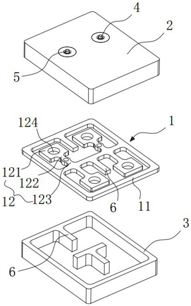
[0076] combine figure 1 and figure 2 As shown, a cross-coupled filter according to Embodiment 1 of the present invention includes a resonant structure 1, an upper cover 2, a lower cover 3, a signal input port 4 and a signal output port 5, wherein the upper cover 2, the lower cover The structure of the board 3 , the signal input port 4 and the signal output port 5 can be referred to the above description, and will not be repeated here, but mainly introduces the structure of the resonant structure 1 .

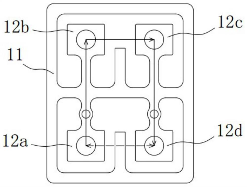
[0077] Such as figure 2 As shown, the filter formed by the resonant structure 1 of Embodiment 1 of the present invention is a fourth-order filter, which includes a frame 11 and two rows of resonant units integrally formed in the frame 11, each row of resonant units includes two resonators 12, That is, four resonators 12 are arranged in the frame, and for the convenience of description, these four resonators are defined as resonator 12a, resonator 12b...resonator 12d, wherein,...

Embodiment 2

[0083] combine Figure 4 and Figure 5 As shown, a cross-coupled filter according to Embodiment 2 of the present invention includes a resonant structure 1, an upper cover plate 2, a lower cover plate 3, a signal input port 4 and a signal output port 5, wherein the resonance of Embodiment 2 of the present invention The filter formed by the structure is also a 4th-order filter, and the difference from Embodiment 1 is, as Figure 5 As shown, the resonator 12a and the resonator 12b in the same row, the resonator 12c and the resonator 12d are mainly electrically coupled, and the resonator 12b and the resonator 12c in different rows are mainly magnetically coupled. The resulting cross-coupling (defined as the first cross-coupling) between the resonators 12a and 12d of the row is predominantly electrical, as opposed to the predominantly magnetic coupling between resonator 12b and resonator 12c. That is to say, between the resonator 12b and the resonator 12c, and between the resonat...

Embodiment 3

[0087] combine Figure 7 and Figure 8 As shown, a cross-coupled filter according to Embodiment 3 of the present invention includes a resonant structure 1, an upper cover 2, a lower cover 3, a signal input port 4 and a signal output port 5, wherein the upper cover 2, the lower cover The structure of the board 3 , the signal input port 4 and the signal output port 5 can be referred to the above description, and will not be repeated here, but mainly introduces the structure of the resonant structure 1 .

[0088] Such as Figure 8 As shown, the filter formed by the resonant structure 1 of Embodiment 1 of the present invention is a 6-order filter, which includes a frame 11 and two rows of resonant units integrally formed in the frame 11, each row of resonant units includes three resonators 12, That is, six resonators 12 are set in the framework. For the convenience of description, these six resonators are defined as resonator 12a, resonator 12b ... resonator 12f, wherein, resona...


PUM


Abstract

The invention discloses a cross-coupled filter, which comprises a resonance structure, the resonance structure comprises a plurality of rows of resonance units, each row of resonance units comprises at least two resonators, and the two adjacent resonators in the same row are mainly electrically coupled or magnetically coupled; coupling formed between every two adjacent resonators of every two adjacent rows of resonance units is mainly based on electric coupling or magnetic coupling, the multiple sets of adjacent resonators of every two adjacent rows of resonance units are coupled in the mode that electric coupling is mainly based on magnetic coupling or magnetic coupling is mainly based on magnetic coupling and electric coupling is mainly based on alternating, and at least one set of crosscoupling is formed. According to the invention, miniaturization and light weight are realized in terms of structural characteristics, and low loss and good harmonic characteristics are realized in terms of electrical performance.

Description

technical field [0001] The present invention relates to a filter, in particular to a cross-coupling filter. Background technique [0002] The recent demand trend for filters is miniaturization and high quality. In particular, the communication components used in the small base stations of 5G communications are smaller in size and more in demand than the previous macro base station products. Therefore, the components used in the product must also achieve high-quality miniaturization, light weight, and a structure suitable for mass production. [0003] The filters currently used in small base stations are usually dielectric waveguide filters and traditional metal coaxial filters. The dielectric waveguide filter can be miniaturized and lightweight, and the manufacturing cost is low, but its loss and harmonic characteristics are worse than that of the metal coaxial filter. Traditional metal coaxial filters have better loss and harmonic characteristics than dielectric waveguide...

Claims


Application Information

Patent Timeline
IPC IPC(8): H01P1/20H01P7/00
CPCH01P1/2002H01P7/00
Inventor 李敦穁罗仁虎尹泽李强
Owner PROSE TECH CO LTD
Why Eureka
Try Eureka